I have a 24V, 3.5A dc motor. Which circuit would works best for my motor? 4 NPN transistor or 2 PNP and 2 NPN transistor?

I have a 24V, 3.5A dc motor. Which circuit would works best for my motor? 4 NPN transistor or 2 PNP and 2 NPN transistor?
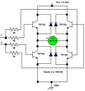
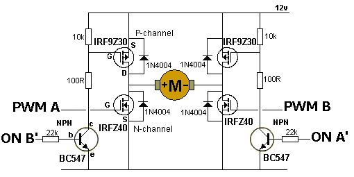
The second design only works at 5V so is unsuitable for your 24V motor.
It looks like the first design also only works at 5V so neither is suitable for your 24V motor.
Is that 3.5A stall current, full-load current or no-load current?
johnwasser:
The second design only works at 5V so is unsuitable for your 24V motor.It looks like the first design also only works at 5V so neither is suitable for your 24V motor.
Ok. What if i change it to 24V. Which circuit would be perfect for my motor?
MarkT:
Is that 3.5A stall current, full-load current or no-load current?
The rated current is 3.5A. Stall current is 17A.
I would just order a free sample from texas instruments of the L293DNE Dual H bridge motor driver get three just to make it worth it! Hey they are free,And good for up to 36 Volts more than you need!! GL hope it works out, Texas Instruments also has PDF's for all the schematics! If you have trouble wiring it up there are plenty of videos on youtube!
Hi, Jimmy, both of those circuits you posted will not work with 24V because of the biasing needed to turn the transistors ON and OFF, particularly the PNP transistors or any in the positive supply side.
Take Willyboielectro's advice and look up how to use L293DNE, although I'm not sure of its current spec.
Tom...... ![]()
Willyboielectro:
I would just order a free sample from texas instruments of the L293DNE Dual H bridge motor driver get three just to make it worth it! Hey they are free,And good for up to 36 Volts more than you need!! GL hope it works out, Texas Instruments also has PDF's for all the schematics! If you have trouble wiring it up there are plenty of videos on youtube!
How do you expect a L293 to cope with the 17A stall current then? It's rated at 0.6A
These current levels need a MOSFET bridge, no question. Some of the Pololu ones
are probably up to it.
You need something like this:
http://www.ebay.com/itm/60A-High-Power-MOS-Dual-Channel-H-bridge-DC-Motor-Driver-Module-/331266660096?pt=LH_DefaultDomain_0&hash=item4d21081700
Another possiblity is this kit: THB6064 MassMind Stepper Motor Driver Kit. I have used it to run 3.5 amp stepper motors. Watch out for drivers based on the Toshiba TB6560 chip, they have a bad track record for blowing up.
Bob
The kit I suggested above would not be right for a non-stepper motor however.
Here's one that may be suitable: http://www.ebay.co.uk/itm/Semiconductor-BTS7960B-Stepper-Motor-Driver-43A-H-Bridge-Drive-PWM-For-Arduino-/370970102887?pt=UK_BOI_Industrial_Automation_Control_ET&hash=item565f8a8c67
While I am sure that it won't take 47A continuous with such a small heatsink, it may well be OK for the 17A stall current of your motor.
TomGeorge:
Hi, Jimmy, both of those circuits you posted will not work with 24V because of the biasing needed to turn the transistors ON and OFF, particularly the PNP transistors or any in the positive supply side.Take Willyboielectro's advice and look up how to use L293DNE, although I'm not sure of its current spec.
Tom......
What if i use a darlington transistor? BDV66B and BDV67B.
Hi, its not the component specs that is the problem with that circuit.
It is the circuit component configuration/layout.
Tom..... ![]()
TomGeorge:
Hi, its not the component specs that is the problem with that circuit.
It is the circuit component configuration/layout.Tom.....
Then how can i modified the circuit?
I haven't read the whole thread so maybe you answered this already, but why are you rolling your own when there are off-the-shelf solutions?
This list shows a number of Pololu products that meet your voltage and current requirements.
JimboZA:
I haven't read the whole thread so maybe you answered this already, but why are you rolling your own when there are off-the-shelf solutions?This list shows a number of Pololu products that meet your voltage and current requirements.
Im doing school project. My task is to design and fabricate a motor driver for my motor.
what type of h bridge circuit can work for my 24V dc motor?
motor specs - rated current is 3.5A. Stall current is 17A.
file:///M:/Temp/ARDUINO%20UNO/DATASHEETS/TC-4428.pdf
Do you understand how to drive an H-BRIDGE ?
1-Do you know how to control the on, off , forward, reverse ?
2-Do you know how to control the speed ?
3-Do you have ANY electronics experience ?
4-How much are you willing to spend ?
Here's some plug & play solutions:
http://www.trossenrobotics.com/store/p/6508-L298-Dual-H-Bridge-Motor-Driver.aspx?feed=Froogle&gclid=Cj0KEQjw7b-gBRC45uLY_avSrdgBEiQAD3Olx0J1ZPcBaLjUtzFWpGbu3RzxYrPhIIxVBDLgFftqU9IaAj858P8HAQ
http://www.robot-electronics.co.uk/acatalog/Motor_Controllers.html
http://www.antratek.com/md22-24v-5a-motordriver
If you want to build it yourself , see attached schematics and datasheet.
I recommend the RFP30NO6LE MOSFET (60V, 30A), LOGIC LEVEL TYPE
You will need GOOD TO-220 heatsinks:
You will have to drill and tap a 4-40 thread hole in the heatsink as it does not come with a hole.
The drill bit and tap are sold together and you just need a centerpunch and a drill to do it.
It's not rocket science. With four of the mosfets I recommended , with the heat sinks linked , it should meet your requirements.
One minor note. Don't forget to buy a small tube of thermal paste at Radioshack when you buy the heatsinks (or order them online on their website).
RFP30N06LE.pdf (189 KB)
jimmy12:
I'm doing school project. My task is to design and fabricate a motor driver for my motor.
OK, so the problem is that both of the original circuits are wrong. Sadly, you require a level of design skill even to pick out good from awful suggestions on the Internet.
Here's a proper one, with a good tutorial on the page.
Addendum: Even then, I'm not so sure about it ...
That's why they make ICs especially for the purpose.
