Hi @ the bad news is that the arduino pin output does not support 40mA output.
The recomended maximum that must be drained from an Arduino output is 20mA. But this is the maximum, and normally you don't work with the maximum.
PS: Sorry for my mistake, Mr. @wildbill is correct.
could you please indicate a suitable diode (D1) reference for this voltage and current ? I guess this is more useful for inductive loads than resistive load, but use it anyway?
Hello 6v6GT, can you please elaborate a bit on how to design the Arduino circuit so that if it fails, the heater is turned off ?
I will implement at software level, that in case of errors on temperature senor, the heater will be off. but on hardware level, I don't really see what I can do more?
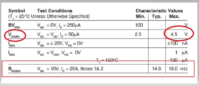
The parameter is Vgs(threshold) = 4.5V
That is when the gate starts to get the MOSFET to conduct, NOT FULLY conduct.
IXTP60N10T is not a logic level MOSFET.
Rds(on) is usefull to calculate power dissipation in the transitor :
P=Rds(on)* I²
5Watts would need a heatsink to dissipate properly i guess.
Pay attention to supply enough Voltage to the gate to exceed Vgs(th) in order to fully "open" the transistor
pay attention to supply enough current to the gate so it charges up correctly (Igss) (seems to be no issue when values are below 20mA for arduino, but this does not matter when using an optocoupler that has it's own power supply for the emmitter
The Mosfet: IRLB3034PbF mentioned in post #12 looks good for direct drive by a 5 volt Arduino pin and has a very low RDS(on), quoted at 4.5 volts, of 1.7mOhms. This should dissipate less than 0.5 watts at 15 amps. You can then use a simple circuit similar to the one in post #2
Having said that, if you get a mosfet with a higher RDS(on), you may not need so much heating wire because the mosfet itself should get hot enough for most purposes.
@JCA34F
I Will start with an arduino nano, but at some point i would also like to add connectivity thanks to a Wemos D1 or similar ESP8266, where the logic levels are only 3.3V so i think to go ahead with an optocoupler before the transistor, good idea ?
The IRFB7437PbF is similar to the IRLB3034PbF but, in exactly the area important for your application, not good enough. Look at the voltage at which the RDS(on) is quoted. It is 6 volts. Don’t even imagine some sort of linear interpolation between this 6 volts and the 5 volts you can drive it at directly with an Arduino of the Uno/Nano caliber. That resistance is critical to you. Every 4 mOhms means another watt to dissipate. If, however, you use the opto coupler circuit which effectively delivers 12volts to the mosfet gate, there is no problem with any of the mosfet options so far seen in that they are all within in specification but still go for the lowest resistance ones to avoid heat generation.
The rule for the "commutation diode" or whatever term you use, is that it is rated for at least the current drawn by the load and at least the voltage applied to the load. No more (is needed), and no less.