The SoftwareSerial library for the Uno comes pre-installed with the Arduino IDE, so you don't need to download it.
john35S:
transmit by table ASCII with TX RX on first UNO in D0 D1
Pins 0 and 1 on the Uno are the hardware serial port Serial. Those pins are used for communication with your computer, such as printing to Serial Monitor and uploading sketches. You may find that you're unable to upload sketches to the Uno when you have something connected to pins 0 and 1. So I recommend that you not use those pins. You can use any pins on the Uno for SoftwareSerial. If you are going to use pins 0 and 1, then it is silly to use the SoftwareSerial library, since these pins have hardware serial capability, which is greatly superior to software serial.
1. This is the type of connection being described in Post#1 of @pert between your two UNOs using Software Serial Ports.
Figure-1:
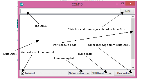
2. This is the sketch that controls LED1, LED2 and LED3, LED4. (1) You enter HL from the InputBox of Serial Monitor (Fig-2) and click on the Send Button (choose Line ending tab at No line ending option); as a result, LED1-LED2 of UNO1 will be ON-OFF; LED2-LED3 of UNO2 will also be ON-OFF.
(2) You enter HH from the InputBox of Serial Monitor (Fig-2) and click on the Send Button (choose Line ending tab at Newline option); as a result, LED1-LED2 of UNO1 will be ON-ON; LED2-LED3 of UNO2 will also be ON-ON.
Figure-2:
Sketch of UNO-1:
Your sketch may be something like this (untested):
#include<SoftwareSerial.h> //SoftwareSerial.h file was included in my PC when I installed IDE
SoftwareSerial SUART(4, 5);   //SRX = 4, STX = 5
char x, y;

void setup()
{
    Serial.begin(9600);
    SUART.begin(9600);
    pinMode(2, OUTPUT);
    pinMode(3, OUTPUT);
}

void loop()
{
    byte n = Serial.available();  //checking if there is any data in Serial FIFO Buffer
    if(n == 2)   //there are 2 data bytes in Buffer
    {
        x = Serial.read();    //bring out the first data byte from FIFO Buffer
        if(x == 'H')              //checking if it is character H that has come from InputBox of Serial Monitor
        {
            digitalWrite(2, HIGH);
        }
        else                         //the first data byte that has come from the InputBox of Serial Monitor is L
        {
            digitalWrite(2, LOW);
        }

        y = Serial.read();     //bring out the 2nd data byte from FIFO Buffer
        if(y == 'H')
        {
            digitalWrite(3, HIGH);
        }
        else
        {
            digitalWrite(3, LOW);
        }
        SUART.write(x);     //send first data byte to UNO-2 over Software Serial Port named SUART
        SUART.write(y);     //send 2nd data byte to UNO-2
    }
}
Sketch of UNO-2:
Follow Sketch-1 and try to write few lines and then we will complete.
The linked library will automatically packetize your data, transmit it, and parse it on the other Arduino for reliable transfer. The library can transfer individual bytes, ints, floats, arrays, and even whole classes! It's also downloadable through the Arduino IDE's Libraries Manager (search "SerialTransfer").
john35S:
in your soft, what is HH and HL ???
where is L ??? that no undestand.
HH for HIGH and HIGH; that means you are sending HIGH commands to ignite LED1 and LED2.
HL for HIGH and LOW; that means you are sending HIGH commands to ignite LED1 and LOW command to turn-off LED2.
and son on....
There are only four combinations:
HH
HL
LH
LL
The ASCII codes of characters H and L can be found in the following Table.
I see the code for H and L colon 4 row 8 = 48 for H and for L colon 4 row C = 4C
e.g. for W colon 5 row 7 = 57 Right ???
now, what is that 0x ??? in 0x48
The second question in my post number #5 For the Wires in D2 in D3 on the two UNO cards and one Portable PC only, no using STX and SRX pins ??? Please give me your solution.
1. One PC and two UNO based UART connection is this:
Figure-1:
(1) Make the following connections:
Connect DPin-5 (STX = TX-pin of Software UART Port) of UNO-1 with DPin-2 (Digital Pin 2) of UNO-2.
Connect DPin-4 (SRX = RX-pin of Software UART Port) of UNO-1 with DPin-3 (Digital Pin 3) of UNO-2.
Connect GND pin of UNO1 with GND pin of UNO-2.
Connect LED1 + R1 circuit with DPin-2 of UNO-1.
Connect LED2 + R2 circuit with DPin-3 of UNO-1.
2. Note:
48 is decimal forty eight = 4x10 + 8x1
0x48 (zero axe four eight) is 48 in hexadecimal base = 4x16 + 8x1 = 72 in decimal.
GolamMostafa:
The OP is using UNO which has no Serial1 Port. Can SerialTransfer.h Library be used to create software serial port? Any example will be appreciated.
Yes, the library works with all serial stream objects (hardware, usb, and all types of softwareserial). All you have to do to make it work is pass the softwareserial class as argument to the begin() member function instead of Serial1.
Power_Broker:
Yes, the library works with all serial stream objects (hardware, usb, and all types of softwareserial). All you have to do to make it work is pass the softwareserial class as argument to the begin() member function instead of Serial1.
description
// for UNO 1  with 2 butons SW1 SW2 on analoginput A0; output D2 for SW1, D3 for SW2
// for UNO 1  with 2 butons SW3 SW4 on A1 ;  output D4 for SW3, D5 for SW4
// for UNO 1  with 2 butons SW5 SW6 on A2 ;  output D6 for SW5, D7 for SW6
// for UNO 1  with 2 butons SW7 SW8 on A3 ;  output D8 for SW7, D9 for SW8
// and for UNO 1  with 1 buton SW9    on A4
//       for UNO 1  with 1 buton SW10   on A5
// ALL butons analoginput by Resistors PULLDOWN
// each pin D2 D3 D4 D5 D6 D7 D8 D9 with LED and resistor
// D10 and D11 are LED output to UNO2 with Serialcom declared mySerialspe
// ...
// on UNO2 , LED1 High when SW9 High only and this level Tx to HC05 module
// on UNO2 , LED2 High when SW10 High only and this level Tx to HC05 module
// ...

// to download in UNO 1
//...
#include<SoftwareSerial.h>
SoftwareSerial mySerialspe(10,11); //Serial com between Uno1 and Uo2 cards, pins 11 and 12
SoftwareSerial bluetoothSerial(0,1); //Serial comm to module HC05, pins 1 and 2

  // UNO 1  First input A0
int sensor1Pin=A0;
int sensor1Value=0;
float tension1;
int val1;
int LedPin3 = 3;
int LedPin4 = 4; // this Leds 3 or 4, selected output by tension level on A0

   // second input A1
int sensor2Pin = A1;
int sensor2value = 0;
float tension2;
int val2;
int LedPin5 = 5;
int LedPin6 = 6; // this leds 5 or 6, selected output by tension level on A1

  // 3th input A2
int sensor3Pin = A2;
int sensor3value = 0;
float tension3;
int val3;
int LedPin7 = 7;
int LedPin8 = 8; // this leds 7 or 8, selected output by tension level on A2

  // 4th input A3
int sensor4Pin= A3;
int sensor4value = 0;
float tension4;
int val4;
int LedPin9 = 9;
int ledPin10 = 10; // this leds 9 or 10, selected output by tension level on A3

void setup(){
// declare the outputs for two leds and the inputs for buttons-sensors
Serial.begin(9600);
pinMode(LedPin1,output);
pinMode(LedPin2, output);
pinMode(sensor1Pin, input);
}

void loop(){
// read the value from the sensor1
val1=analogRead(0);
tension1=(val1*4,9)/1000;
Serial.print("value read after converter= ");
Serial.print(val1);
Serial.println("Digital read= ");
Serial.print(tension1);
Serial.print ( Volts);
Serial.println();
delay(200);


}


//   Is't  Correct this first half of sketch ?   ?
// I suspect an error when I will WRITE this line: tension2=(val2*4,9)/1000;
// it's (2*4,9)/1000; or I must write "val" by other way ?

//  John