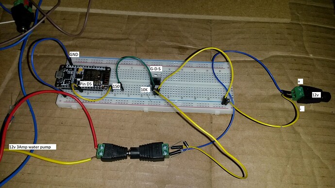
UPDATE: As Wawa pointed out, I was off kilter, here. I had forgotten that we're talking about a NODEMCU, here, NOT an Arduino. Thus, the supply voltage [and thus the gate drive voltage] is 3.3V and not 5V. And, the available drive current is 12mA, not 40mA -- huge difference! So, the prevailing indication is that the STP36NF06L MOSFET is just not able to PWM drive that pump, and that a MOSFET more like the one suggested by larsgregersen, the IRL540, which I agree is a better choice, but still might not be enough. This one, maybe: IPP052N06L3GXKSA1, or this one: STP200N3LL These two have rather high input capacitance, but it should still only take 12mA a few hundreds of nS to turn them on, and by the time a couple of volts exist at the Gate, they are already able to handle tens of Amps at their Drain. And, they aren't all that expensive. The edits, below, indicate my errors, and offer insights from my new POV 
It sounds like the MOSFET isn't turning ON/OFF fast enough. To test for this, try using the Blink Sketch, but use Pin 5, instead of the usual LED_BUILTIN constant:
void setup() {
  pinMode(5, OUTPUT);
}
void loop() {
  digitalWrite(5, HIGH);
  delay(1000);
  digitalWrite(5, LOW);
  delay(1000);
}
If that works, then try adding a 47 to 100pF capacitor across the 150Ω resistor. That will "punch" the Gate with a burst of current, to turn the MOSFET ON/OFF faster [i.e. it will overcome the Gate capacitance].
If that doesn't do it, then try increasing the 150Ω resistor to 220Ω 275Ω [but leave the capacitor there].
If that doesn't do it, then you may need to drive the MOSFET with a transistor or MOSFET driver -- or find a MOSFET with a lower Gate Capacitance, that can still drive your pump or find a MOSFET that functions better at a 3.3V Gate voltage. OR, use a lower PWM frequency [though, that may make the pump hum like a SOB!].
If the Blink Sketch doesn't turn the pump on and off, then, first, try a different Digital Pin, and if that doesn't do it, then try all the other Digital pins. If none of them properly drive the MOSFET, then perhaps the MCU board is bad. If that isn't it, then I don't know what the heck is going on, other than the MOSFET is in some kind of failure mode where it is leaking so much current at the Gate, that your MCU can't drive it. To test for that, put an Ammeter (or Multimeter set to read current -- start with the highest current range) between the MCU pin and the MOSFET Gate. If it's more than a microamp, then something is wrong (though, the current might jump and settle back to zero -- that's normal)! If it's on the order of milliamps, then something is VERY wrong -- and VERY weird! Try a different MOSFET!
If the current reading is at zero, even on the lowest current setting [it might jump and then settle back to 0, which is normal -- as long as it comes back to zero, then it's good], then, perhaps more than one of the MCU pins is bad [or all of them are bad] -- try others until you run out, or you find one that will drive the MOSFET properly. Then, try your PWM sketch, but with the capacitor in parallel with the 150/220Ω resistor. Also, you could set your Multimeter to DC Volts [20V], and monitor the MCU pin. The voltage should go to ~5V ~3.3V, then to ~0V, and back, once a second. If the voltage drops more than a few tenths of a volt, when it should be 5V 3.3V or doesn't even come close to 0, when it should be 0, then the MCU pin is not driving the MOSFET properly -- Try watching the +5V +3V pin -- it should stay at +5V +3.3V. If it drops below 4.5V 3.0V, then check the Vin pin (assuming you are powering your MCU board that way). In other words, make sure the Power Supply is supplying adequate voltage for the whole 2 second period of the Blink test.

