Yess!! Got it!!
Thanks for the help... But i've tried powering them that way earlier....tho i just used 4 cells...Should i try using 6 cells??
Yess!! Got it!!
Thanks for the help... But i've tried powering them that way earlier....tho i just used 4 cells...Should i try using 6 cells??
Your schematic is pretty good.
But I'm asking myself to which IO-pins are the input-pins of the L293D conncected?
Here is a schematic of the Adafruit motor shield V1 (my guess at what the OP has).
The V2 shield uses the TB6612 motor driver.
Wait, can you please explain this in a simpler language??
My dumb mind does not gets what this is.
You have to say the real name for what you mean with "this"
We are not WhatsApp-ing we discuss seriously technical things
@StefanL38 inquired "to which IO-pins are the input-pins of the L293D conncected?" This shows how the shield connects to the Uno.
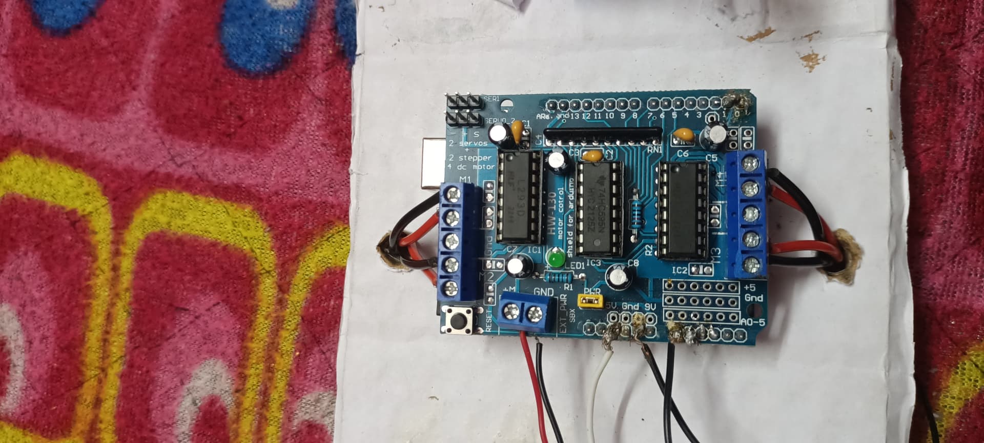
OP, is the shield that you have an Adafruit motor shield V1 or a copy thereof?
@nah_but_a_begginer please post a high-resolution picture of your motorshield.
maybe two pictures one showing the hole shield a second picture with zoomed in on the chip so that the printed letters on the chip are readable
Before posting the second picture check if the letters are really readable on the picture.
Oh okay, got it. Which pins are the IO pins??
Oh i see..Well the digital pins of arduino are connected to the digital pins of Motor driver. & the AO-5 pins & Gnd 5v of arduino are connected to the AO pins & gnd, 5v of arduino...
I dont guess i have a copy of Motor shield
You have indeed an older version of the motor-shield
Here is some documentation and tutorial about it
This shield uses a so called shift-register for driving the L293D-chips.
This means you can drive it only with the special motor-shield-library
that is required for this shield.
You can't drive the motor by a simple digitalWrite(pin,LOW(HIGH)
Your case is another example that ALL the details are important. Especially about hardware.
best regards Stefan
Ooh, Okay I'll read it..
Thanks for the help!!
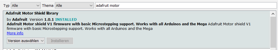
You can install the library from the library-manager of the arduino-IDE.
Make sure that you install version V1

Here is a demo-code for DC-motors
best regards Stefan
Using the code, only one of the motor is working. While the others aren't even moving.
it is time that you start reading documentations.
In the PDF-file I linked above there is a chapter DC-motors
and on page 43 there is an example-code with comments
#include <AFMotor.h>
AF_DCMotor motor(2, MOTOR12_64KHZ); // create motor #2, 64KHz pwm
on page 44 starts the explanation of the AF_DCMotor motor-class
AF_DCMotor motorname(portnum, freq)
This is the constructor for a DC motor. Call this constructor once for each
motor in your sketch. Each motor instance must have a different name as
in the example below.
Parameters:
port num - selects which channel (1-4) of the motor controller the motor will be
connected to
freq - selects the PWM frequency. If no frequency is specified, 1KHz is used by
default.
best regards Stefan
Okay sir!! I'll start reading the documentation!!
You appear to be out of time. Hint:
I/O pin that can be used for input or output under program control
Output a pin that just outputs s signal, it does not generally read.
Input a pin generally used to place data on so the processor can read it.
D/A Digital to analog, it outputs a voltage under program control.
Input pin, a pin the processor reads to get information.
A/D Analog voltage input.
There are many variations of this but that is under program control.
This tells me I've got a lot to learn here.
Alright, I've read the document. I guess i got it that what i gotta do for the motors. I'll try to rearrange the wires & rewrite the code by myself