Why my Photoresistor values do not change when I light the sensor

hello, it's my first time on arduino help forum so i apologize if it's the wrong méthode of message sending and for my bad english.

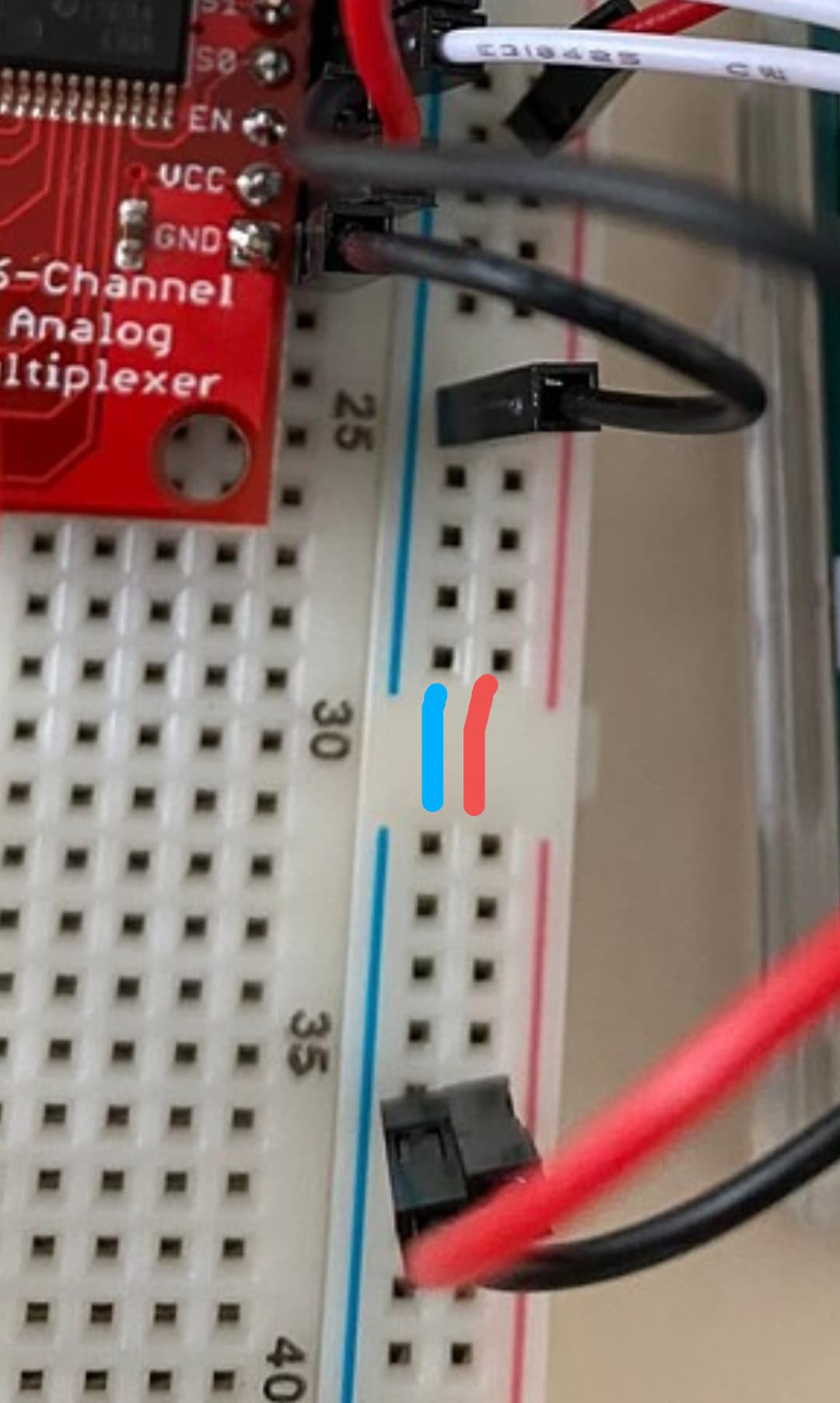
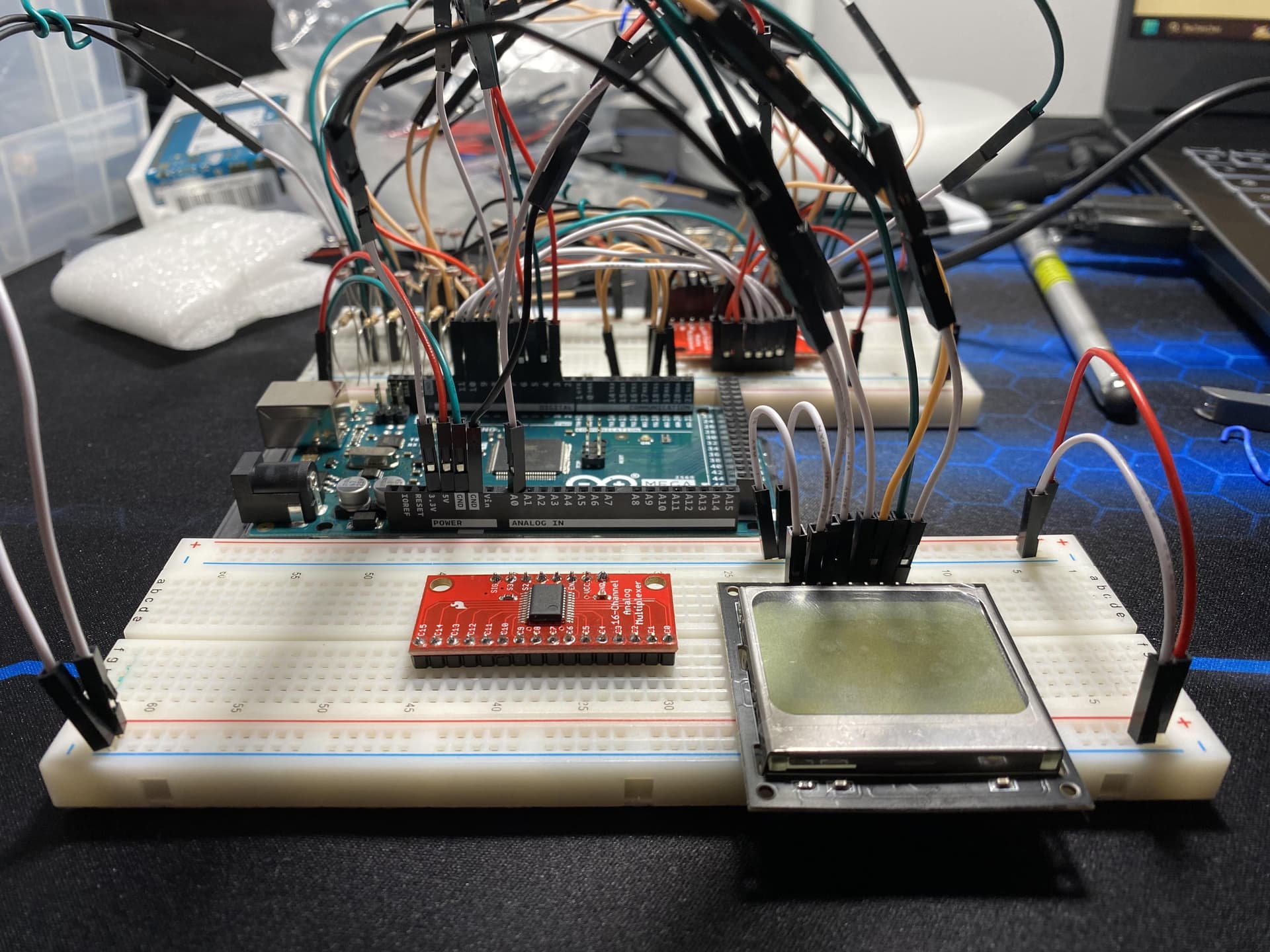
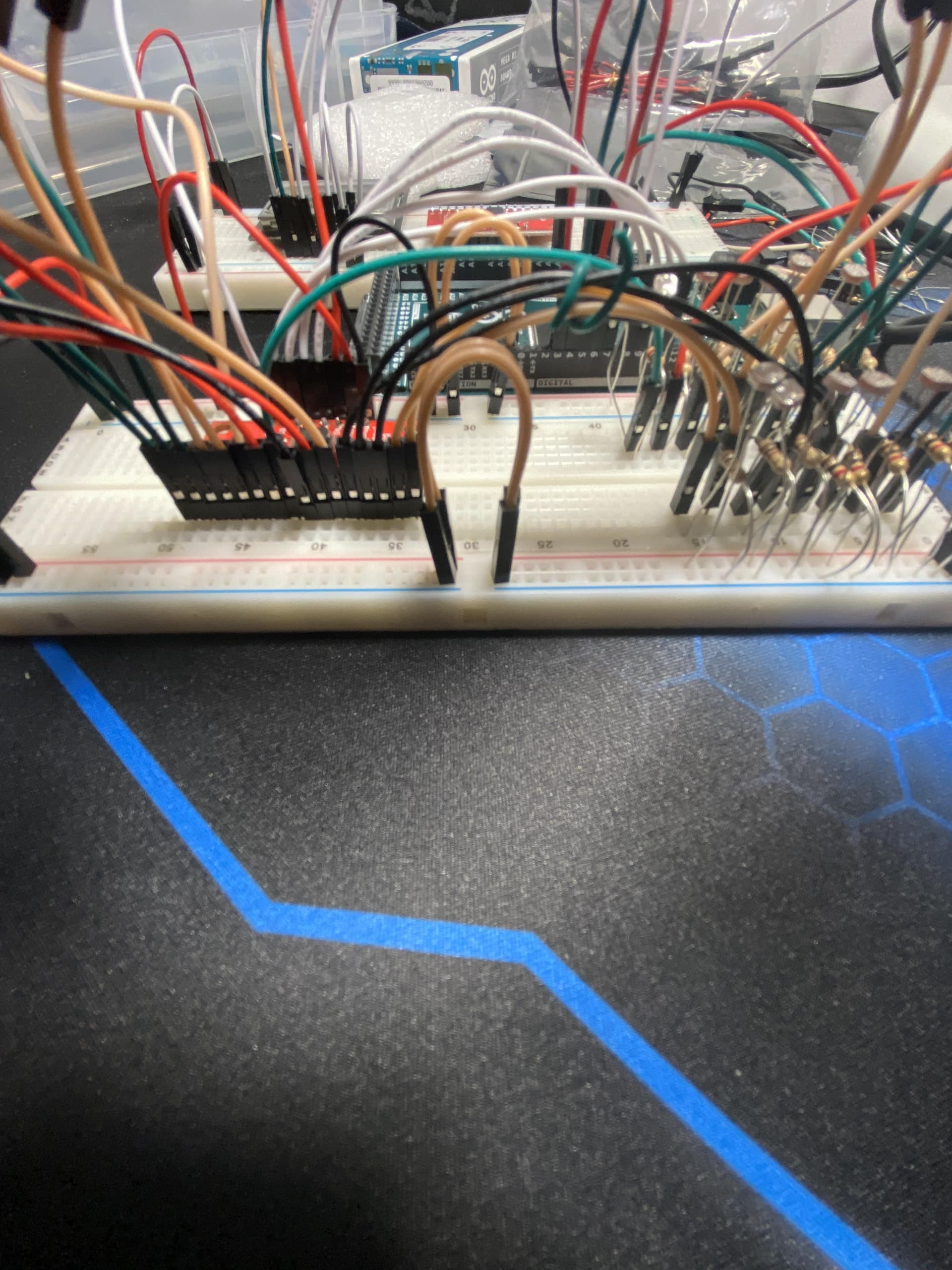
my problème is, when start my code and when i open my monitor, the values of my lux sensor don't change even if i light the sensor, i'm asking where is the error, if the photorésistor doesn't match with multiplexor 16 to 1, or if there is a mistake in my electronical, i'm stuck since 3 days on that. please enlighten me on this subject.

code :


// Mux control pins
int s0 = 8;
int s1 = 9;
int s2 = 10;
int s3 = 11;

// Mux in "SIG" pin
int SIG_pin = A0;

void setup() {
  pinMode(s0, OUTPUT);
  pinMode(s1, OUTPUT);
  pinMode(s2, OUTPUT);
  pinMode(s3, OUTPUT);

  digitalWrite(s0, LOW);
  digitalWrite(s1, LOW);
  digitalWrite(s2, LOW);
  digitalWrite(s3, LOW);

  Serial.begin(9600);
}
void loop() {
  // Loop through and read only channel 0 and channel 1
  for (int i = 0; i < 2; i++) {
    Serial.print("Lux value at channel ");
    Serial.print(i);
    Serial.print(" is : ");
    Serial.println(readMux(i));
    delay(1000);
  }
}

float readMux(int channel) {
  int controlPin[] = {s0, s1, s2, s3};

  int muxChannel[16][4]={
    {0,0,0,0}, //channel 0
    {1,0,0,0}, //channel 1
    {0,1,0,0}, //channel 2
    {1,1,0,0}, //channel 3
    {0,0,1,0}, //channel 4
    {1,0,1,0}, //channel 5
    {0,1,1,0}, //channel 6
    {1,1,1,0}, //channel 7
    {0,0,0,1}, //channel 8
    {1,0,0,1}, //channel 9
    {0,1,0,1}, //channel 10
    {1,1,0,1}, //channel 11
    {0,0,1,1}, //channel 12
    {1,0,1,1}, //channel 13
    {0,1,1,1}, //channel 14
    {1,1,1,1}  //channel 15
  };

  // loop through the 4 control pins
  for (int i = 0; i < 4; i++) {
    digitalWrite(controlPin[i], muxChannel[channel][i]);
  }

  // read the value at the SIG pin
  int val = analogRead(SIG_pin);

  // convert the value to lux
  float voltage = (val * 5.0) / 1024.0;
  float resistance = (5.0 - voltage) * 10000.0 / voltage;
  float lux = 500.0 / resistance; // Simplified conversion formula, you can replace it with a more accurate formula if needed.

  // return the lux value
  return lux;
}

Your topic has been moved to a more suitable location on the forum. Installation and Troubleshooting is not for problems with (nor for advice on) your project.

I can't see a problem with your code that would stop it from measuring the change in light level.

It is difficult to understand your circuit from your photographs, but I will look at them again. A schematic diagram would be better. Please Google to find out what a schematic should look like. It is not the same as a colourful but confusing wiring diagram (such as a Fritzing Breadboard View).

Have you tried connecting your light sensor directly to the Uno analog input, without the multiplexer?

ok thanks for your work, I didn’t know, but now it’s clearer for me from where I have to place my subjects.

1 Like

Aha!

Breadboard power rails are split at the centre!

You need to connect them like this:

1 Like

so this is my monitor, as we can see, when i light the sensor, it make no differences, this is the main problem of my project.

let's talk about your suggestion.
when i plug the first sensor dirrectly at A0 it's working, but in my project i have a lot of sensor and i have to use the multiplexor because there is not enought numeric plugs in a classic arduino

okay i'll try

I have one of those breadboards, but much prefer the solid power rails.

All though you can accidently insert something wrong without much happening if you leave them split.

Kind of helpful but more of a hinderance. :wink:

Finally, my sensor now reacts to my light. Thank you for solving my problem and especially for broadening my knowledge.

thanks you all to have spend your time on my problem

2 Likes

hello there is someone who can help me on the update version of this circuit ? there is a short circuit and i don't know where it is ....


sorry if my photos are bad...

it's fine, i found the bug .

Hi, @pvac

Now is the very important time for you to draw a schematic of your project.
An image of a hand drawn schematic will be fine, include ALL power supplies, component names and pin labels.

Reverse engineer your project.

Tom... :grinning: :+1: :coffee: :australia:

2 Likes

This topic was automatically closed 180 days after the last reply. New replies are no longer allowed.