Why resistor in parallel with digital input?

Hi all!

In all examples I can find on internet, every one use a resistor together with a switch.

I would like to know why?

On this page for example: Multiple Limit Switches Problem

First:
Why not just use ground+digital input?

Second:
If I want to have a tiny led indication together with a input how would I do that? Connect?
(I don't want any logic behind the led, only if a input is active or not(if a switch is on or off))

Third:
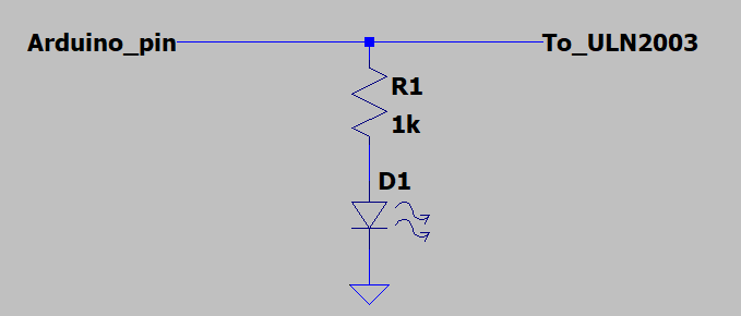
If I want to have the I/O as a output to a ULN2003A and want to have a led that indicates if a Output is on or off how would I connect that, and why?

Forth:
Can you use the voltage that comes from Arduino output or input, or must I use 5V? (Like in many exampels)

I am making planes for a PCB I am constructing, and want to use Arduino Mega or Pokeys 57E,U or Leobodnar BBI-64 Button Box Interface as Input device for switches.

Also I want to use Arduino Mega or Pokeys 57E,U as Output, together with ULN2003A that will control Leds, Relays and Light Bulbs.

I will construkt "Shields" for Arduino, Pokeys and Leobodnar, so you can decide what input device you want or output device.

And reason for the questions is that I wan't led indication bothe for inputs and outputs on my PCB.

Links:
Pokeys is much like Arduino
Pokeys Manual
LeoBodnar is smal an easy to connect.
LeoBodnar BBI-64 Button Box Interface

If someone could direct me to a explanation and or diagram of these things it would be nice!

Best regards Jacob

The resistors keep the pin at a known state when the switch is not closed to take the pin to HIGH (or LOW if it is wired that way)

You can turn on the built in pullup resistor of a pin to take it normally HIGH by using INPUT_PULLUP in pinMode()

2 Likes

Many people get it wrong or make it more complicated than it needs to be. What you say is correct and works for nearly all situations as long as the internal pullup resistor is enabled.

See e.g. here for suggestions in a thread from someone asking the exact same question: A proper way to use a button and an LED

Easiest way is to just connect a series resistor and LED to the digital output that goes to the respective input on the ULN2003.

For what....?
But in general, you can choose and it depends on the situation & what you're doing.

A switch between ground and a digital port makes the digital port go 0 when the switch is on. But when the switch is off, there's nothing that decides whether the digital port is 1 or 0. The port is said to be floating. A resistor is added. If switch goes from port to ground, the resistor goes from port to +5V or vice versa. This way the digital port is always pulled to the opposite of what the switch is doing. When switch is off, the resistor decides the state of the port. 10 kOhm is quite enough to pull the port. When the switch is on, the resistor still pulls with its 10 kOhm, but the switch is 0 Ohm and wins the tug-of-war. At that point, 0.2 mA runs through the resistor from +5V to ground.

[edit]
Of course, there are internal pullup resistors. They simplify the circuit a lot, but the main idea remains the same.

With many thanks to LarryD

Nice explanation. but why is S1 the worst thing to do?

As it seems that my initial thought to connect ground to switch and switch to digital input, is the best way. I want to use that one. becouse then it works with pokeys and leobodnar to.

And acording to the forum fot the software Mobiflight no pull up resistor is needed, and arduino will use the internal.

But then it comes to how to connect a led in series with the button, what is the best way to do that?

Did you in fact click the link I gave you? That thread as I recall lists at least 3 ways and also discusses what works best (and what doesn't).

Yes of course

I read it as that I should use this:

sw1led1x

But can I use this if I am going to use 54 inputs. Of corse it depends on leds. But very smal week leds, I want to use something like this: https://www.electrokit.com/produkt/hsmg-c170-led-gron-0805-15mcd/

But it seams that almost all leds ar 20mA that means + resistor = Power 0.056 W

54*0.056=3.024 W

= 0.6048 A

Maybe it is best to have extarnal power source?

Sounds like you're good to go :slight_smile:

Can you show with a picture?

Easiest way is to just connect a series resistor and LED to the digital output that goes to the respective input on the ULN2003.

I have only seen that they connect on the output from the ULN2003?

Is ther any pros, cons with that?

Example with stepper motor:
5edd8699996374ce21202d29ca5f7ec6c6c2d618_2_500x301

https://forum.arduino.cc/t/reproducing-uln2003-motor-driver-board-capacitor-needed/639090

It's just one leg of resistor to arduino pin and to input pin on uln2003, other leg to anode of led, cathode of led to GND. 1k for the resistor should work OK.

Pleas can you show with a picture, I understand better that way. And no mix up.

image

Super thank you! But why 1k?

Also what would happen if I by mistake set a input as a output or the other way around if I connect as described, with leds and resistors?

5V (Vcc) - 1.5V (forward led drop, approx.) = 3.5V / 1000 = 3.5mA = very safe/conservative current level to draw from a digital IO pin.
Based on: Ohm's law (electronics 101) combined with information from the microcontroller datasheet.

It's intended to function as an output.
If you mistakenly set this output as an input, then nothing much happens at all. The ULN2003 won't be driven, the led won't light up (actually, if it's a very efficient smd led, it may light up very dimly if you write HIGH to the input port).
Based on: microcontroller datasheet.

Conclusion: it pays to (1) learn the basics of electronics and (2) read the datasheets of the components you use.

Sure. I have a product that I used to sell that has 18 digital and count inputs like this. Each LED consumed (IIRC) about 3mA. Modern LEDs are pretty efficient and very bright.

One of the best ways to find out why things are hooked up the way they are is to do it your way and see what happens. After smoking a few parts, it becomes obvious.

As to Why, it's the law. Ohm's Law.

1 Like

Do you mean that the 5V comes from arduino output pin?

In that case I wonder if I realy can use Pokeys as an alternative. Because I think that gives 3.3V at the output.

I unfortunately don't understand everything I want when it comes to electronics. I am just an electrician that have discovered the wonderful world of being able to create my one PCB with Kicad.

I have made one, so far threw JLCPCB, but that was only a sort of connection board, and this time I want to make a more advanced board.

Befor I construct everything that want. I must be sure.

It will be 3 Ardunios or Pokeys connected with 54 I/Os used. It is more than 150 signals that must be correct.

100 or so, inputs and over 50 output.

Best regards Jacob

:rofl:

To expensive

1 Like

Yes.

Will work too, but led will be less bright. You could reduce the resistor to e.g. 510 Ohms.

Build it on a breadboard, test thoroughly, and then make a PCB.

There will be errors in your first PCB version. I can almost guarantee it. Live with it!