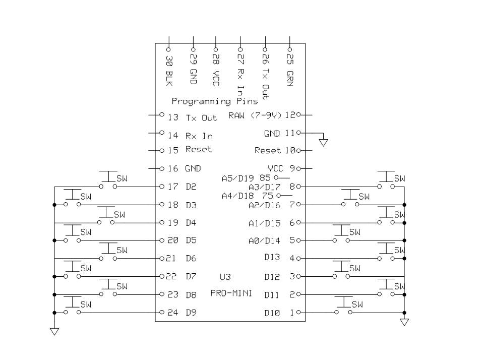
I am trying to make a very simple RF remote with 12 buttons. This will be the sole purpose of the project so there will be no problem using all the digital pins for all the buttons. See the attachment for what I have so far. The resistors are only daisy chained together for GND. Note the bent legs that connect to the buttons; those ends of the resistors are not daisy chained. The schematic is a mess (sorry) so I'll explain anything you need.
My essential question is this: will it work? Thanks!
connecting a switch to digital pins is what the NANO is designed for.
as long as you have proper pull-up or pull-down resistors, your concept will work.
using digital pins 0 and 1 run the risk of interfering if you are using those pins for communication.
don't overlook the fact that the analog pins A0 thru A7 are available as digital inputs. ( the NANO has the extra 2 A/I pins 6 and 7) not found on the UNO with DIP chip.
and, if you want to save pins, AND.... AND you NEVER push two buttons at the same time, you can use analog pins with multiple buttons.
If you set each digital pin to INPUT_PULLUP, which turns on the internal pullup resistor, you won't need to wire up any of those resistors. Each button will have a digital pin on one side and ground on the other - no +5V needed.
dave-in-nj:
don't overlook the fact that the analog pins A0 thru A7 are available as digital inputs. ( the NANO has the extra 2 A/I pins 6 and 7) not found on the UNO with DIP chip.
Not so sure, but I have read somewhere that pin A6 and A7 are only usable as analog input.
but even as an analog input, you feed it with a weak pull-up , and the button press brings it low.
you have something to measure.
so, every analog input can be used to sense a button press.
if you are completely certain that no two buttons can be pressed at the same time,
you can use a voltage divider between buttons and have 4 or more buttons, and know which is pressed based on the voltage.
many LCD shields use one analog input as the pin for all the buttons.
ilguargua:
Not so sure, but I have read somewhere that pin A6 and A7 are only usable as analog input.
Ciao, Ale.
you are correct.
A6 and A7 are direct feed to the ADC, there is no digital circuit on the board/chip level. so there is no internal pull-up and such.
however, you can use an external resistor and read the ADC value,
and have a simple logic, if the put is above some value, say 500, then it is high, then it is on one state,
if it is low, say below 400, then it is in a different state.
Thank you all for your input! That's all good information to know. Yes, I am completely certain that only one button will be pressed at a time. I've thought about using a voltage divider, but I just wanted to keep it super simple (and I'm running low on my stock of assorted resistors, 10k is what I have in an adequate quantity). I thought that this design would require the least amount of effort, but of course I could be wrong.
majhi:
I thought that this design would require the least amount of effort, but of course I could be wrong.
If you wire a button between pin and ground, you can use the internal pull-up. No extra components required. Just be aware that a ptessed button will read high.
Thank you all for your input! That's all good information to know. Yes, I am completely certain that only one button will be pressed at a time. I've thought about using a voltage divider, but I just wanted to keep it super simple (and I'm running low on my stock of assorted resistors, 10k is what I have in an adequate quantity). I thought that this design would require the least amount of effort, but of course I could be wrong.
How can you be certain that only one button would be pressed at a time? With the buttons as close as they look in your picture, there might even be accidental double button presses.
Since you have plenty of pins, just to use INPUT_PULLUP, and wire each switch to it's own pin, and to a common ground on the other side of the switch. Then a double button press would merely send your program two different inputs, which could be handled any way you like.
This is what I'm looking at now. I removed the RF transmitter for the moment to make the schematic more readable. Let me see if I understand how this works because I'm interested in the process as well, not just the end result. The buttons all share a common GND and the same legs go to digital pins. When a button is pressed, it "interrupts" (or activates? I don't know if these are NO or NC buttons) the connection to GND on that particular button and the Arduino detects the state change. Is that correct?
CrossRoads:
You need 2 wires to each button, connect to diagonal pins.
One is to Gnd, the other to the microcontroller.
Doh! I should have known that because the state change relies on bridging the two "channels" of the switch. I really need to take a class on small electronics or something.
most tact switches are normally open push buttons.
with the internal pull-up in the chip itself, the value is high all the time.
Since (we expect) the switch is open, when you press a button(switch)
the line is brought to ground or 0 volts.
the state of the pin goes from high to low.
The only thing I see wrong is your Fritzrig.
typically the long side of the switch/button is common. you have the ground and the pin on the long side.
many of us use diagonal pins to guarantee no mistakes.
majhi:
... I really need to take a class on small electronics or something.
I see that you have highlighted "diagonal pins" in CrossRoads post. Those small 'tactile' buttons have four terminals. They are in pairs - two of them go to one side of the switch, and two go to the other side. when you push the button all four are connected. By attaching to diagonals, you are assured that you are actually bridging one side to the other (if you pick adjacent pins, you have a 50% probability of getting it right.)
As for a class, look around your town/city for a 'public access' class (or series of classes) on basic Arduino. But the very best education for a hobbyist is to hang around here and read (and re-read) posts by some of the heavies, like CrossRoads, sterretje, dave-in-nj, el supremo and LarryD - among others. Folks (like me) with less posts and less karma are also good to read, but the gold of this site is the preponderance of many 'eager-to-help' gurus. I learn something new every time I visit arduino.cc.
Those push buttons can be confusing If you don' have a multimeter. It can be a usefull present for Sinterklaas or Santa If you have one, measure the push button in both 'positions'.
dave-in-nj:
don't overlook the fact that the analog pins A0 thru A7 are available as digital inputs. ( the NANO has the extra 2 A/I pins 6 and 7) not found on the UNO with DIP chip.
Correction: Only A0 through A5 can be used as digital inputs. A6 and A7 are just inputs to the analog input multiplexer and have no digital I/O hardware.
You can connect a switch to those analog inputs and use analogRead() to see if the input was HIGH (1023) or LOW (0). They don't have an internal pull-up resistor so you need an external pull-up or pull-down resistor.