Well this encoder work with my Arduino UNO?
ERCF 1 05SPI 360 Z
ercf-spi.pdf (697.3 KB)
If so, does someone have code that can be used to read the angular position? And a wiring diagram?
Well this encoder work with my Arduino UNO?
ERCF 1 05SPI 360 Z
ercf-spi.pdf (697.3 KB)
If so, does someone have code that can be used to read the angular position? And a wiring diagram?
In which units?
Degrees or radians.
Have fun!
When you pick a library for the encoder, it will have sample code for what you want.
Assuming there is a library for this hall effect rotary encoder with SPI output, of course. I'm betting there isn't one.
I always assume there is one.
just a quick thrown together demo-code.
needs a test if it will work
// MACRO-START * MACRO-START * MACRO-START * MACRO-START * MACRO-START * MACRO-START *
// a detailed explanation how these macros work is given in this tutorial
// https://forum.arduino.cc/t/comfortable-serial-debug-output-short-to-write-fixed-text-name-and-content-of-any-variable-code-example/888298

#define dbg(myFixedText, variableName) \
  Serial.print( F(#myFixedText " "  #variableName"=") ); \
  Serial.println(variableName);

#define dbgi(myFixedText, variableName,timeInterval) \
  { \
    static unsigned long intervalStartTime; \
    if ( millis() - intervalStartTime >= timeInterval ){ \
      intervalStartTime = millis(); \
      Serial.print( F(#myFixedText " "  #variableName"=") ); \
      Serial.println(variableName); \
    } \
  }

#define dbgc(myFixedText, variableName) \
  { \
    static long lastState; \
    if ( lastState != variableName ){ \
      Serial.print( F(#myFixedText " "  #variableName" changed from ") ); \
      Serial.print(lastState); \
      Serial.print( F(" to ") ); \
      Serial.println(variableName); \
      lastState = variableName; \
    } \
  }

#define dbgcf(myFixedText, variableName) \
  { \
    static float lastState; \
    if ( lastState != variableName ){ \
      Serial.print( F(#myFixedText " "  #variableName" changed from ") ); \
      Serial.print(lastState); \
      Serial.print( F(" to ") ); \
      Serial.println(variableName); \
      lastState = variableName; \
    } \
  }
// MACRO-END * MACRO-END * MACRO-END * MACRO-END * MACRO-END * MACRO-END * MACRO-END *

unsigned long MyTestTimer = 0;                   // Timer-variables MUST be of type unsigned long
const byte    OnBoard_LED = 2;     // onboard-LEDESP32 / ESP8266
//const byte    OnBoard_LED = 25;  // onboard-LED Raspberry Pi pico
//const byte    OnBoard_LED = 13;   // onboard-LED uno, mega

/* Encoder-Pin
1 (VCC)  Red 5V
2 (GND) Grey  GND
3 (SCLK)  Grey  SCK (13)
4 (MOSI)  Grey  MOSI (11)
5 (MISO)  Grey  MISO (12)
*/

#include <SPI.h>

// Define chip select pin
const int CS_PIN = 10;

void setup() {
  Serial.begin(115200);
  Serial.println("Setup-Start");
  PrintFileNameDateTime();

  SPI.begin();

  // Configure SPI settings
  SPI.beginTransaction(SPISettings(1000000, MSBFIRST, SPI_MODE0));

  pinMode(CS_PIN, OUTPUT);
  digitalWrite(CS_PIN, HIGH); // Deselect sensor
}

void loop() {
  BlinkHeartBeatLED(OnBoard_LED,250);

  if ( TimePeriodIsOver(MyTestTimer,100) ) {
    readPrintEncoder();
  }
}


void readPrintEncoder() {
  // Read encoder position
  digitalWrite(CS_PIN, LOW); // Select sensor
  uint16_t rawData = SPI.transfer16(0x0000); // Read 2-byte data
  digitalWrite(CS_PIN, HIGH); // Deselect sensor

  // Process 14-bit data (mask upper 2 bits)
  uint16_t position = rawData & 0x3FFF;

  // Convert to degrees (0-360°)
  float angle = (position * 360.0) / 16383.0;

  // Display results
  Serial.print("Raw Position: 0x");
  Serial.print(rawData, HEX);
  Serial.print("\tAngle: ");
  Serial.print(angle, 2);
  Serial.println("°");
}


// helper-functions
void PrintFileNameDateTime() {
  Serial.println( F("Code running comes from file ") );
  Serial.println( F(__FILE__) );
  Serial.print( F("  compiled ") );
  Serial.print( F(__DATE__) );
  Serial.print( F(" ") );
  Serial.println( F(__TIME__) );
}


// easy to use helper-function for non-blocking timing
// explanation see here
// https://forum.arduino.cc/t/example-code-for-timing-based-on-millis-easier-to-understand-through-the-use-of-example-numbers-avoiding-delay/974017
boolean TimePeriodIsOver (unsigned long &startOfPeriod, unsigned long TimePeriod) {
  unsigned long currentMillis  = millis();
  if ( currentMillis - startOfPeriod >= TimePeriod ) {
    // more time than TimePeriod has elapsed since last time if-condition was true
    startOfPeriod = currentMillis; // a new period starts right here so set new starttime
    return true;
  }
  else return false;            // actual TimePeriod is NOT yet over
}


void BlinkHeartBeatLED(int IO_Pin, int BlinkPeriod) {
  static unsigned long MyBlinkTimer;
  pinMode(IO_Pin, OUTPUT);

  if ( TimePeriodIsOver(MyBlinkTimer,BlinkPeriod) ) {
    digitalWrite(IO_Pin,!digitalRead(IO_Pin) );
  }
}Created an experimental library for the ERCFS rotary encoder.
It is experimental as part of the information is not mentioned in the datasheet.
I have contacted the manufacturer to get this info.
The missing parts are the SPI mode to use, and if data is MSB or LSB
As I have no hardware to test, could you verify if it works?
Thanks,
Thanks. I'm waiting for it to come in. Will keep you posted.
Got email from the company, they stated SPI_MODE1 and MSB.
So I am updating the library to version 0.1.1.
Do you have a wiring diagram with code for how the library is supposed to work? I see the example in GitHub but it looks like only one pin (pin 9) is used?
//
//    FILE: ERCFS_HW_SPI.ino
//  AUTHOR: Rob Tillaart
// PURPOSE: demo dump millis + position.
//     URL: https://github.com/RobTillaart/ERCFS
//

#include "ERCFS.h"

ERCFS re(9);  //  hardware SPI

void setup()
{
  while(!Serial);
  Serial.begin(115200);
  Serial.println(__FILE__);
  Serial.print("ERCFS_LIB_VERSION: ");
  Serial.println(ERCFS_LIB_VERSION);
  Serial.println();

  SPI.begin();

  bool b = re.begin();
  Serial.print("BEGIN:\t");
  Serial.println(b);
}


void loop()
{
  uint16_t position = re.getRawValue();
  Serial.print(millis());
  Serial.print("\t");
  Serial.println(position);
  delay(50);
}


//  -- END OF FILE --
9 would be the CS pin used in your UNO. The SPI pins for the encoder are in the datasheet and the pins for the UNO are well described all over internet.
Thanks @ledsyn for your answer.
You could change the CS pin 9 to any free IO pin you have of course.
And the datasheet has more to say, but I think @remusconnor should do some work too.
Right, datasheet say SS, which equals CS.
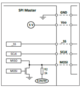
So the other two signal wires "SCLK" and "MOSI" are not used?
Yes they are.
Follow those instructions.
I'm a bit puzzled by that shared MISO / MOSI arrangement. Is that supposed to be a open collector output, since the pullup? That picture describes 3-wire SPI which OP said he was going to get.