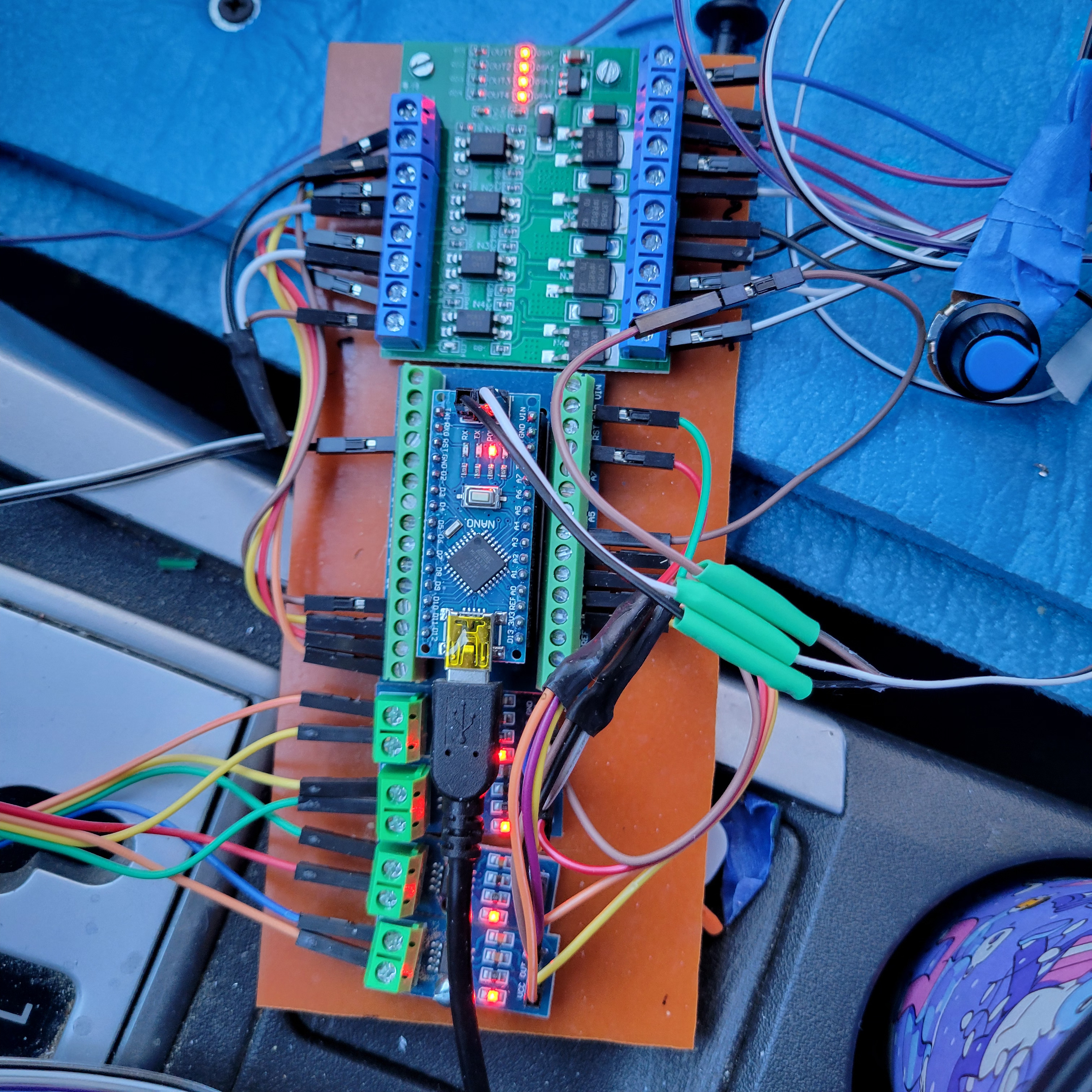
Bottom is 4 712 5a current sensors.Toyota injectors run through current sensors and to ECU.
Middle is Nano.
Top is PWM.
Car runs fine.
Top is to create altered injector signal for alternate injectors (PWM).
Here code
const int analogPins[4] = {A0, A1, A2, A3}; // Analog input pins
const int outputPins[4] = {2, 3, 4, 5};     // Digital output pins
const int potPin = A4;                      // Potentiometer pin
const int potPowerPin = 6;                  // Power pin for potentiometer

void setup() {
  for (int i = 0; i < 4; i++) {
    pinMode(outputPins[i], OUTPUT);         // Set output pins as OUTPUT
  }
  pinMode(potPowerPin, OUTPUT);             // Set potentiometer power pin as OUTPUT
  digitalWrite(potPowerPin, HIGH);          // Supply power to the potentiometer
}

void loop() {
  int potValue = analogRead(potPin);        // Read potentiometer value
  float scaleFactor = map(potValue, 0, 1023, 15, 100) / 100.0; // Map to scale factor

  for (int i = 0; i < 4; i++) {
    int signalValue = analogRead(analogPins[i]); // Read analog input

    if (signalValue > 204) {                // Check if voltage > 1V (204/1023*5V)
      unsigned long startTime = millis();   // Start timing
      while (analogRead(analogPins[i]) > 204) {
        // Measure duration of signal > 1V
      }
      unsigned long duration = millis() - startTime;

      unsigned long outputDuration = duration * scaleFactor; // Adjust duration

      digitalWrite(outputPins[i], HIGH);   // Output high signal
      delay(outputDuration);               // Hold for adjusted duration
      digitalWrite(outputPins[i], LOW);    // Output low signal

      delay(50);                           // Add a delay for stability if needed
    }
  }
}
It don't seem to be pulsing from current sensors, when car is running.
All grounds and powers check out.
Since the car runs, pulses are obviously passing through the current sensors.
They have proper power and ground. But no blinking, or...
They seem to be sending a constant 2.2v to the Nano. I need them to measure pulse durations.
Any wild or solid advice?
Ah. You caused me to look up if the sensor actually blinks, and it does NOT. Then I noticed in the specs that it centers on 2.5v (with a 5v input).
Which means I programmed the Nano incorrectly, from the get-go.
I have a cheap oscope but couldn't get it to work properly. (My lack of familiarity). And yes I used a VOM.
So now I'm off top dead center and ready to tackle it again.
Thank you very much.
To measure a DC current with an ACS712, you need to subtract 521 from the value.
But the value could be negative if the current flows the other way. This could fix that. int signalValue = abs(analogRead(analogPins[i]) - 512);
Leo..
OK thanks. I need the anaolg reading to start and end a 12v pulse on a separate PWM.
Apparently the current ramps up for approximately half its duration.
It's max current should be about 1amp.
I could probably use about .2amps to trigger the Nano. It's not super critical because I have a pot attached to the Nano to adust the output pulswidth ratio.
I will be able to greatly control the output ratio, if everything works as expected.
It's a 5a ACS712 so maybe a 492 or 532 (approx.) would be the triggers.
I could program 492,...and the wires are easily reversable if I have the wrong polarity.
Does this sound feasable?
BTW I might have blown my scope because at one point I put it on an injector wire, forgetting that it spikes well above 100v. Without attenuation its only rated for 60v.
My line of code (with absolute) converts any polarity of the current to 0 to ~189 (5 Amp version of the ACS). So 1Amp would be a value of about 38.
Leo..
So the 189 should replace the 512 in your code? or find and insert a certain value within the 0-189?
I think the latter, seems like the Nano needs a specific number; unless that's on a different line.
Will 1amp add/subtract 1v from 2.5?
So .2amp would be 38 x .2? Then subtract from 189/2, or about 95?
Very rookie here.
An ACS712 has a bias/idle voltage of VCC/2, which is about 512 when measured with a 10-bit A/D. So no current through the sensor results in an A/D value of ~512.
(analogRead(analogPins[i]) - 512) removes that bias voltage.
No current through the sensor now gives an A/D value of zero.
Current one way adds to that value of 512, current the other way subtracts from 512, which gives negative numbers. If we don't know which way the current will flow, and we want a positive number, then abs() is added.
A 5Amp ACS712 has a sensitivity of 185mV/Amp (see datasheet).
0.185V / 5volt * 1024 = 38 A/D values per Amp.
0.2Amp would be 38 x .2 = an A/D value of about 8
Leo..