Hello, a student and I are working on a project where we're trying to wirelessly control an AC load (like a lightbulb or a doorbell) with a pressure mat that her dog (who can't bark) will step on outside to indicate that he is standing at the door and ready to come inside.
We found this link that has been helpful so far but have been unable to control the light with the pushbutton in the circuit we built:
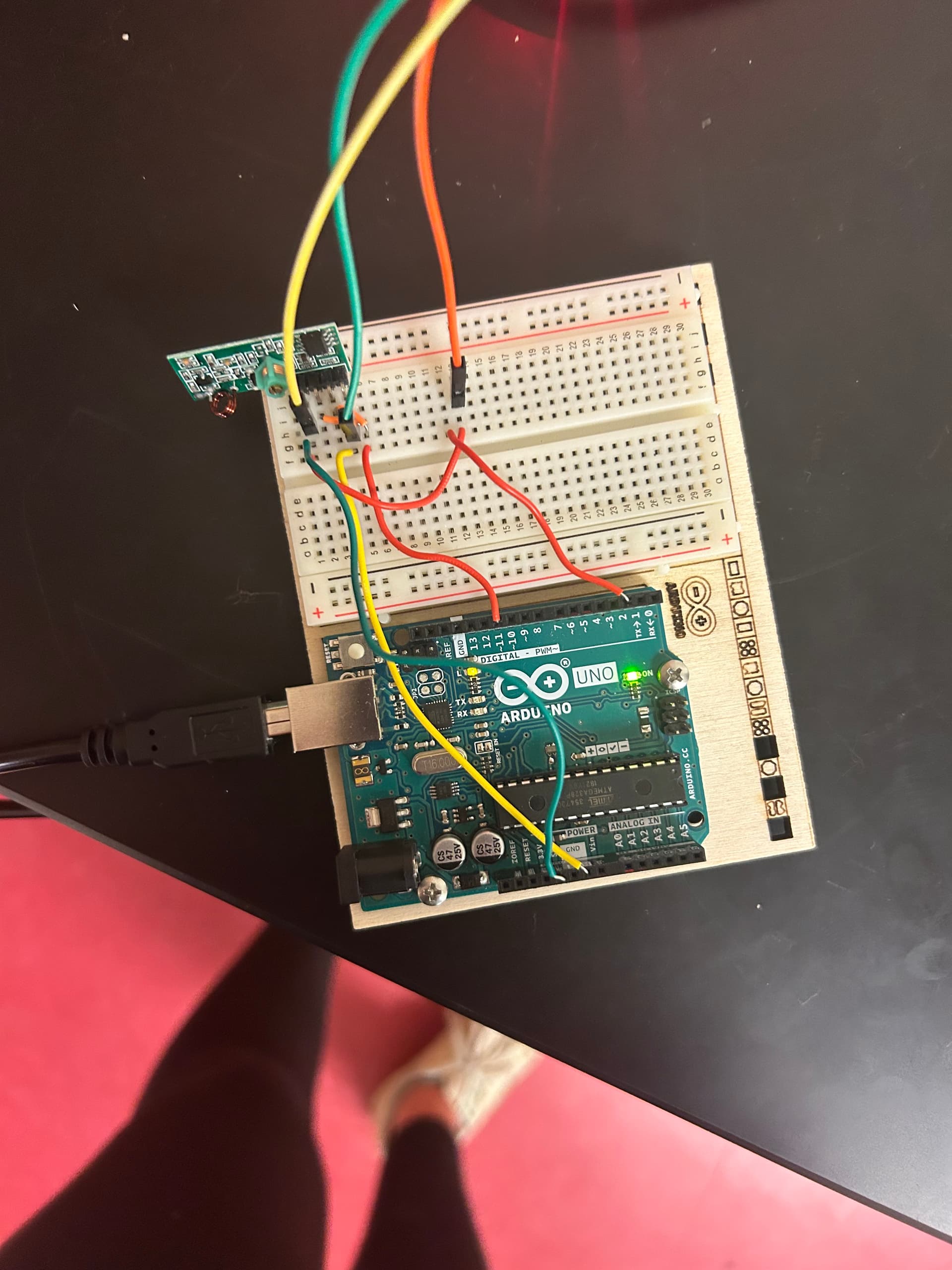
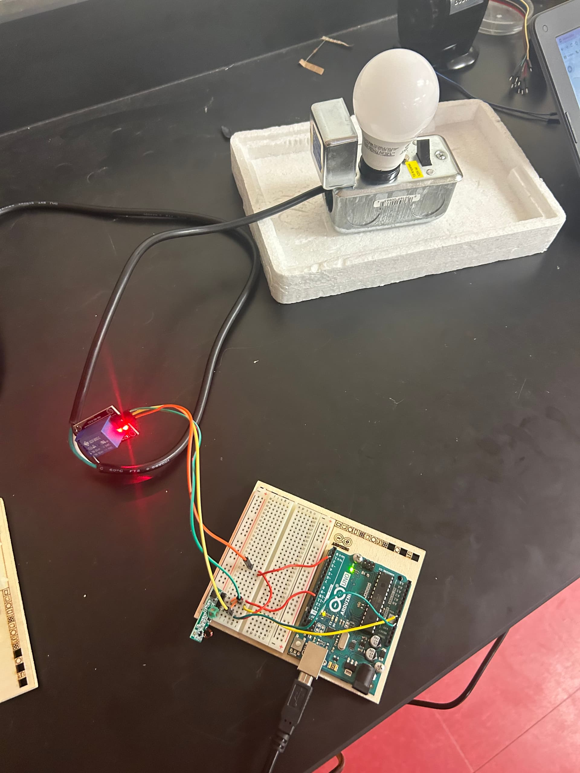
Attached are some pictures of the circuits we've built, and all of the code that we've used and the schematics for the circuits are in the link.
Any help is appreciated!
Transmitter Code
#include <RH_ASK.h>
#include <SPI.h>

const int switch_in = 3;
int state = 0;
char *msg;
RH_ASK driver;

void setup()
{
  driver.init();
  pinMode(switch_in, INPUT);
}

void loop()
{
  if (digitalRead(switch_in) == HIGH && state == 1) {
    msg = "Switch";
    driver.send((uint8_t *)msg, strlen(msg));
    driver.waitPacketSent();
    delay(200);
    state = 0;
  }
  else if (digitalRead(switch_in) == LOW) {
    state = 1;
  }
}
Your link show and is coded for TWO switches. Push one to turn on and push the second switch to turn off. But your code shows only ONE switch. So you are NOT using the code for the link. How did you change the code so only one switch is used? Did you prove the original code worked with two switches before changing?
The relays are the go to way for this as you are doing. That would be adaptable for a range of AC loads, of course. Having said that, an alternate way to control a light might be, on the receiving end, to use a servo to simply flip a light switch. Easy install for any pet owner!
The code that I provided above is from the section in the linked webpage that shows a single switch, titled "Single Device Control with Latching Switch".
We are just realizing that neither the transmitter nor receiver modules seem to have come with antennas... can you confirm? That could be an issue (lol).
I would first code each half without the radio modules to ensure that the code is doing what you think it is.
You can use Serial to send and receive chars in the monitor and see what's going on by adding
"Serial.println("Light on");
And so forth before integrating the wireless connection.
To see how to do that, look up "serial input basics robin2" and check out the excellent guide in this forum. I'd link it but I'm on my phone and don't know how to link forum app pages in other forum threads
If you show a picture, then that will be confirmed. The pictures in the link show modules with coiled antennas. If your devices had the coiled antennas, then you would know. If they don't, then you have different modules from the linked web site.
We just needed to position them within a couple cm of each other - there are internal antennas but they are relatively weak.
We were able to wire in a pressure mat, but the code is setup for a latching switch as opposed to a pressure switch (like a pushbutton). So, as of now, if the dog steps on the mat, he will need to step off, then back on again in order to turn the light bulb off. How can we resolve this so that it's on when he's on the mat and off when he's not on it (as a pressure switch is supposed to function)?