Hey. I wish to know how I could wire an Atmega328p-au with a LoRA RFM95 module, with programming pins also considered.
Thank you!
Hey. I wish to know how I could wire an Atmega328p-au with a LoRA RFM95 module, with programming pins also considered.
Thank you!
Check the documentation for the library you are using.
wait, what? bare chip?
I am using the 433 Mhz bare RFM95 module. Something like this: https://www.aliexpress.com/item/32820691011.html?spm=a2g0o.productlist.0.0.1ebb43839CZixG&algo_pvid=16e983ab-8315-4e7e-9991-fc7d5bfe2985&algo_exp_id=16e983ab-8315-4e7e-9991-fc7d5bfe2985-4&pdp_ext_f={"sku_id"%3A"64778517214"}&pdp_pi=-1%3B192.56%3B-1%3B-1%40salePrice%3BSAR%3Bsearch-mainSearch
If you want help, you will need to provide some basic information to the forum, we are not good at guessing;
Which Arduino are you using ?
Which LoRa library are you using ?
A description of the actual project might be helpful too.
Okay so as I said, I am just using a bare Atmega328p-au chip with a bare LoRA RFM95 module.
I myself don't know which LoRA Library would be good to use. Please advice.
And the actual mission is a LoRA Node prototype which I will be using to put in my garden to transmit temperature values to a receiver in my room. I know I can use an Arduino Uno or anything so, but I also want to experiment around with Atmega, and do this project on a cheap budget.
Uno is exactly for playing around purpose. Bare chip is for people who exactly know what he do and what he will using.
Are you even seen how small is Atmega328p-au chip? Are you expert in soldering?
Yes, I understand the complications of the Atmega328p-au chip. I am good at soldering. That is why I aim to undertake this project.
You could use a UNO, but since its 5V logic you need to add conversion circuits for the 3.3V LoRa module.
By far the easiest Arduino to use would be a 3.3V Pro Mini, it will often be cheaper than a bare ATMega328P processor.
So get hold of a 3.3V Pro Mini and test with that first.
If you then feel the need for a more expensive setup get hold of a ATmega328P and all the other components needed and build a bare bones Arduino.
I've used several of these with my RFM modules:
The have a 328P, regulator, LED, space for an SPI flash chip and on the reverse, a footprint for various RFM modules.
It will save you some soldering and board development time.
Okay, thank you.
For anyone trying to figure out the same thing as me, I wish to tell you that, I got the answer.
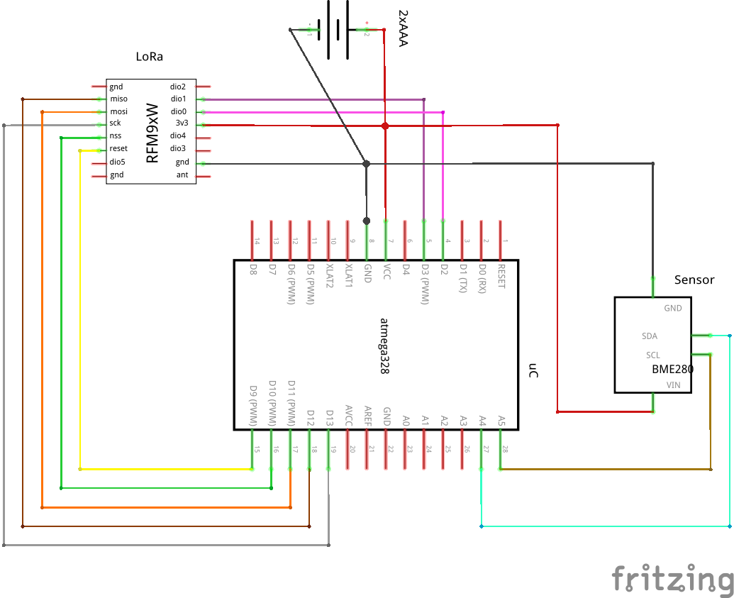
Here is a schematic for the RFM95 Module:
And for the RFM95W Module:
(https://www.thethingsnetwork.org/forum/uploads/default/original/3X/4/a/4a5d1b7c4fa6b5801120e2314b252684547854b9.png)
You may contact me at skygazerbelal@gmail.com for any details.
Yes, but your showing the forum a diagram from the The Things Network website.
Connections and libraries are different for TTN versus LoRa point to point, which is why in post #6 you were asked to describe the actual project.
If you have a transmitter in the garden and the receiver is in your bedroom (as you mentioned in post #7) then your not using a TTN setup .................
Wait, how do you differentiate between the TTN's and normal RFM95 Wiring? Would be helpful if you provide a few schematics.
Generally a schematic shows all components, connections etc. You are missing the power supply for starts, there is no power source. What is the voltage requirement for the RFM92. Where are your decoupling caps and what are there values, a lot is missing. Post a schematic, not a frizzy picture of how you have it wired and links to technical information on all of the hardware components.
Okay, thanks.
Your missing the point made in post #3, the connections do depend on the library you are using. There is no 'one wiring scheme for all', and there are way more than a 'few schematics'
You can run an RFM9x on SCK,MOSI,MISO and NSS, thats four pins.
(Plus power and antenna pins of course)
You may need to run it (depending on the library and function) on SCK,MOSI,MISO,NSS,NRESET,DIO0,DO1 and DIO2, thats 8 pins. DIO0,DIO1 and DIO2 may need to be on specific pins.
So before you can draw a schmatic decide on which library your going to use.
Oh, can you please provide me with the link to a LoRA library that can work on the 4 pins?
Explained here;

