Since your using a 28 pin DIP ATmega328P, its not difficult for you to breadboard the circuit before you design the PCB, its much easier to correct design issues on a breadboard versus a finished PCB.
But dont wire up even a breadboard as per the schematic, you stand a chance of destroying stuff.
if you are using a RA-01 LoRa module you will need to conect RST and DIO0 and possibly DIO1 (depends on LoRa library used)
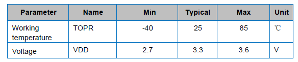
the Atmega328 uses 5V logic the RA-01 uses 3.3 V logic - you will require level converters
GSM modules can draw up to 2 amps when transmitting - make sure your power supplies can supply this
There is a LoRa library that will run on the connections shown, but most of them need at least one more, possibly two pins connected. Check the pin requirements of the library you are using.
The voltage supply, to the ATMega328P and LoRa device looks like its a Lithium battery, since its labelled as 3.7v, If its a lithium battery, that could be 4.2v. What is the maximum voltage for the LoRa module you are using, you will find that information in the devices datasheet ?
What does the ATmega328P datasheet say is the minimum working voltage for a 16Mhz crystal ?
I plan to use a 3.7 Li-battery, I also use 5v to hx711 with a DCDC converter.
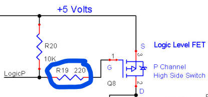
16MHz I will check regarding voltage, but I have 5 V from converter but that is anoption I dont like due to my low power demand. I will switch off as many modules as possible with the mosfet and switch on to send data each 2 h
I wonder if you need a mosfet for power switching. Don't all but the DS18B20 have sleep modes? And the DS18B20 doesn't draw much, so just power it from a 328P pin.