Hi friends!
I am writing to you because I need your help. I have a project and I am standing due to the wiring and computing of two electric motors for Arduino. It seems, that on internet, are very common in a lot of projects, but I have not been able to find any connection scheme. Also, is not easy for me how to computing the electric engines in the arduino IDE. I am new…
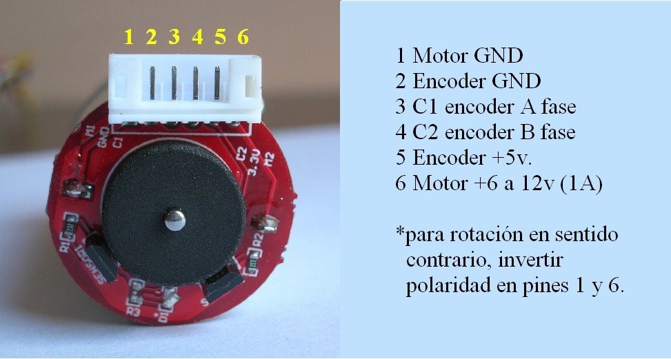
I could to running the engines. This is very easy. But I want to get the steps or the revolutions, rpm. I attached some images of my engine, and what I have done.
- Motor: Uxcell DC 6V 210RPM Encoder Gear Motor with Mounting Bracket 65mm Wheel Kit 1 Set for Smart Car Robot DIY.
- There are 6 wires.
- Use sensor Hall
- Between Arduino UNO and motors I am using the “H”-Bridge: L298N.
I did some conections that works:
Out 1 of L298N: Pin 1 motor GND
Out 2 of L298N: Pin 6 motor.
Other Pins....after waste a lot of hours...no idea...
Thank you very much!!
Link Motor: https://www.amazon.com/210RPM-Encoder-Motor-Mounting-Bracket/dp/B074XRW6XJ

// pins for the encoder inputs
#define RH_ENCODER_A 11
#define RH_ENCODER_B 10
#define LH_ENCODER_A 13
#define LH_ENCODER_B 12

// variables to store the number of encoder pulses
// for each motor
int leftCount = 0;
int rightCount;

int IN1 = 8; //motors
int IN2 = 7; //motors
int ENA = 6; //motors PWM

int IN3 = 5; //motors
int IN4 = 4; //motors
int ENB = 3; //motors PWM

void setup() {

  pinMode(LH_ENCODER_A, INPUT);
  pinMode(LH_ENCODER_B, INPUT);
  pinMode(RH_ENCODER_A, INPUT);
  pinMode(RH_ENCODER_B, INPUT);

   // Motores
    pinMode(IN1, OUTPUT);
    pinMode(IN2, OUTPUT);
    pinMode(ENA, OUTPUT);

    pinMode(IN3, OUTPUT);
    pinMode(IN4, OUTPUT);
    pinMode(ENB, OUTPUT);

  // initialize hardware interrupts
  attachInterrupt(0, leftEncoderEvent, CHANGE);
  attachInterrupt(1, rightEncoderEvent, CHANGE);

  Serial.begin(115200);
}

void loop() {
  Serial.print("Right Count: ");
  Serial.println(rightCount);
  Serial.print("Left Count: ");
  Serial.println(leftCount);
  Serial.println();
  delay(500);

  digitalWrite(IN1, HIGH);
  digitalWrite(IN2, LOW);
  analogWrite(ENA, -125);

  digitalWrite(IN3, LOW);
  digitalWrite(IN4,  HIGH);
  analogWrite(ENB, -125);
}

// encoder event for the interrupt call
void rightEncoderEvent() {
 if (digitalRead(LH_ENCODER_A)== LOW){
     if (digitalRead(LH_ENCODER_B)== HIGH){
             rightCount--;
      } else {
             if (digitalRead(LH_ENCODER_A)== HIGH){
             if (digitalRead(LH_ENCODER_B)== LOW){
             rightCount--;
             }
          }
      }
 }
}

// encoder event for the interrupt call
void leftEncoderEvent() {
  if (digitalRead(LH_ENCODER_A) == HIGH) {
    if (digitalRead(LH_ENCODER_B) == LOW) {
      leftCount++;
    } else {
      leftCount--;
    }
  } else {
    if (digitalRead(LH_ENCODER_B) == LOW) {
      leftCount--;
    } else {
      leftCount++;
    }
  }
}

