I'm working on a portable project using an Arduino pro mini (Atmega328 3.3V 8MHz) that needs to: receive GPS and magnetometer data, process and display this data on 7 segment and OLED displays, save logs to a microSD card, and have few buttons to press.
Since it's portable, I'm powering it with a single 18650 battery that is connected to RAW pin. I'm using a small DC-DC converter to 5V for MAX7219 and 7 segment displays. All other components are running from VCC pin.
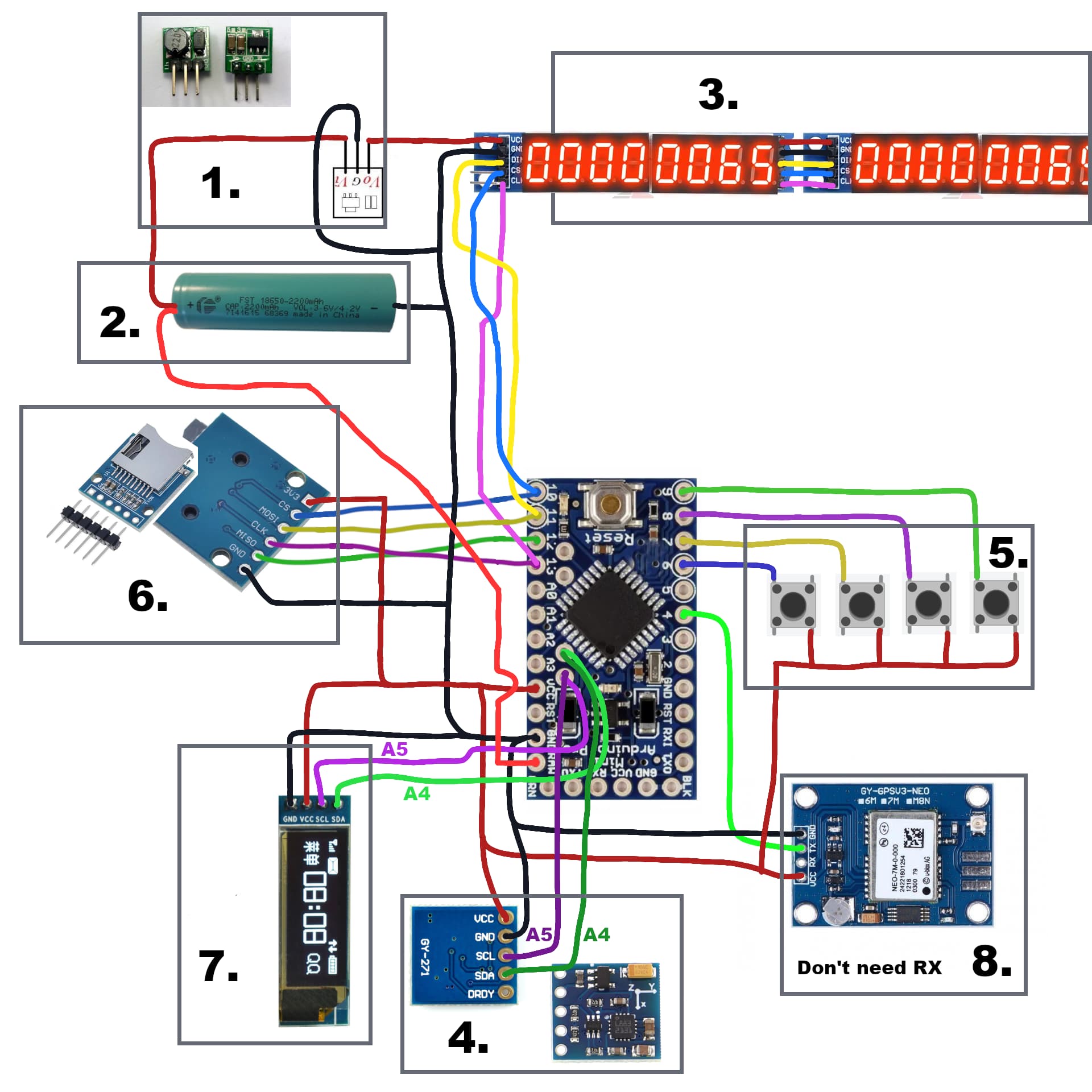
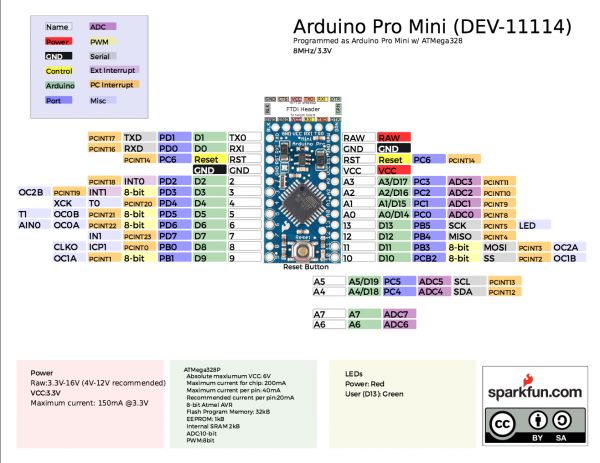
Below is my circuit diagram (sorry if it's messy, I hope you can read it), along with pictures of exact modules I plan to use. I'd love your feedback on whether I've wired everything correctly or if there's some better approach. I'll also provide the Arduino pro mini pinout diagram I followed.
List of modules and components on diagram:
Mini DC-DC converter 0.9-5V to 5V
FST 18650 battery 3.7V 2200mAh
MAX7219 8 digit 7 segment LED display (x2)
GY-271 QMC5883 magnetometer
Buttons (x4)
Arduino microSD card module 3.3V
OLED display 0.91 128x32 px
Ublox NEO-7M GPS module
If you need more details or clarification feel free to ask. Thanks!
The LED display will probably be the biggest load on your battery.
Don't forget that with DC-DC converter, power input will be a little higher than power out, and that the input current at 3V7 will be higher than the 5V current going out of the coverter.
Tom....
If you look up the specs of all your components you may be able to make an energy audit.
So you can see where your energy is going and how long the battery will stay within the acceptable battery output range and the circuits power input range.
Exactly the suggestions I was going to make.
Almost all hobby ‘makers’ only vaguely understand voltage, but are blissfully unaware of current and power / capacity.
Later, we’ll get to regulators/ converters and wire gauges !
Thank you for your answer! I know that those 7 segment displays draw more current than anything else, but I use them for aesthetic purposes. Also I haven’t started my project yet, figuring out what components to buy.
That “MAX7219 8 digit 7 segment LED display” requires 5V so I figured I would just use simple dc-dc converter. Would you suggest anything else? I’m only looking for a few hours of runtime so with a 2200 mAh battery I assume that should be enough. What wire gauges would you recommend?
I would be concerned that the little 3.3V regulator on the Pro Mini would be able to source enough current to supply the parts running on it, particularly the SD card.
I wonder if the things that need 5V could actually run on the battery directly, down to maybe 3.5V. Then instead of the boost converter, you could have an external 3.3V regulator to drive the Pro Mini and other 3.3V parts.
I'd urge you to get the most efficient 7 segment displays you can find. Displays vary widely in their efficiency. You show two banks of 8-digit displays. Is that what you will be using?
Wire gauges won’t be an issue with your current configuration.
I suspect your whole project will draw slightly less than 500mA with all LED digits in operation and other devices - allowing for losses in the converter, so your first guess should be ok. @shermanp notes are worth considering.
Why do you think microsSD card module will have troubles working? I never used it so I don’t have any experience with it, but it will run once every minute or so just to log latest data. If it draws too much current could I for example turn off all other components for a few seconds while it logs the data?
As I already said I want to use 7 segment displays for aesthetics purposes and I need 16 digits. In reality each of those 4 digits segment actually needs about 2V to run. But the big problem is that I don’t have enough pins to run 4 of those 4 digits pieces as each one requires 12 pins. So by using “MAX7219 8 digit 7 segment LED display” I can stack multiple of them and still use only 5 pins. The drawback is that MAX7219 needs 4 - 5.5V
Edit: Would it be better to connect the battery to the 3.3V regulator and power each module from it, rather than using the RAW pin and powering modules from VCC, because of current limitations?
The regulator on the original Sparkfun 3.3V Pro Mini is the MIC5205, which is a 150mA regulator. I doubt the typical clone from the Far East is any better than that. SD cards can draw significant current when erasing and writing, but the current draw can vary a lot from one brand to another. So you really need to determine what each of your devices needs in the way of voltage and current, and figure out how to power them. The advantage of the external 3.3V regulator is that you should be able to find one that provides a lot more current, but still with a very low dropout voltage, and you can fan out its output to everything that will run on 3.3V, including the Pro Mini itself (at its Vcc pin).
I know the MAX7219 datasheet says it needs 4V, but I suspect it will run ok powered directly from an 18650. Then you could not need the boost converter unless there's something else that needs a higher-voltage supply.
At some point you'll need to be specific about the parts you propose using. Then the experts here can opine about what works and what doesn't, and what alternatives might be better.
Kevin Darrah has a nice video on the MAX7219, including daisy chaining two of them.
Thanks! I’ll go on a buying spree, gather all the necessary parts, test the current draw, check if the MAX7219 module can run directly from the battery, and then come back with a clear diagram.
How can I be more specific about the parts I’m using? I’ve tried providing the exact name of each component along with exact image. What should I include for you to know exactly what part it is?
Honestly idk, but good question. I don't plan on storing anything for long on it. I need to get gps data as fast as gps module can handle and display it, and every 10-20 seconds log latest gps position to microSD card. So I think it should be fine.
There is some good advice on that link: "To prevent fire or personal injury". But you are not following that advice. Like I said, a dangerous fault in your circuit.
I'm disappointed that you have not yet asked what it is that makes your circuit dangerous. Maybe you have given up on the project. But in case that's not true, I must tell you, for your safety.
It does not appear that your 18650 battery has built-in over-discharge protection. Most 18650 do not have that. A few do have protection, and these have a small circular PCB at the negative terminal and a metal strip running along the length of the battery which lets that PCB monitor the voltage if the battery and disconnect it from the circuit if that voltage falls below the 2.75V limits recommended in the link you shared.
Your DC-DC converter will not provide such protection.
If allowed to over-discharge, the battery can become permanently damaged. When re-charged, it can heat up, burst into flames or explode. This is no joke. You will have heard stories about lithium batteries causing problems like this, I'm sure.
So you will need a over-discharge protection module in your circuit.
Sorry if I disappointed you. I didn’t have much free time yesterday, and I wanted to read the whole post on my own and figure it out. But anyway, thank you for mentioning it!
Btw where should I place the over discharge protection? I plan to connect the battery to both a 3.3V regulator and a dc-dc converter for 5V, and then use those two to power the Arduino and all other modules. Should I place the over discharge protection right after the battery, before the regulator and converter?