I have bought a 30A relay to replace a10A one, however this relay has a in1+ ANS a in1- socket (the 10A one only has in1).
I am not sure why it has +and- and are not sure how to wire it up. Does anyone know?
Do you have a link to the datasheet?
A regular relay coil will work with AC or DC and the terminals are not polarized. Solid state relays don't have coils and the control input is usually polarized.
Relay or relay module?
Post a link to the relay so we know what we are trying to solve. It is like saying my blue car in the next town won't start, why?
Relay module

You didn't mention anything about your board, I expect you have 5V arduino borad.
Two images, which one you have??
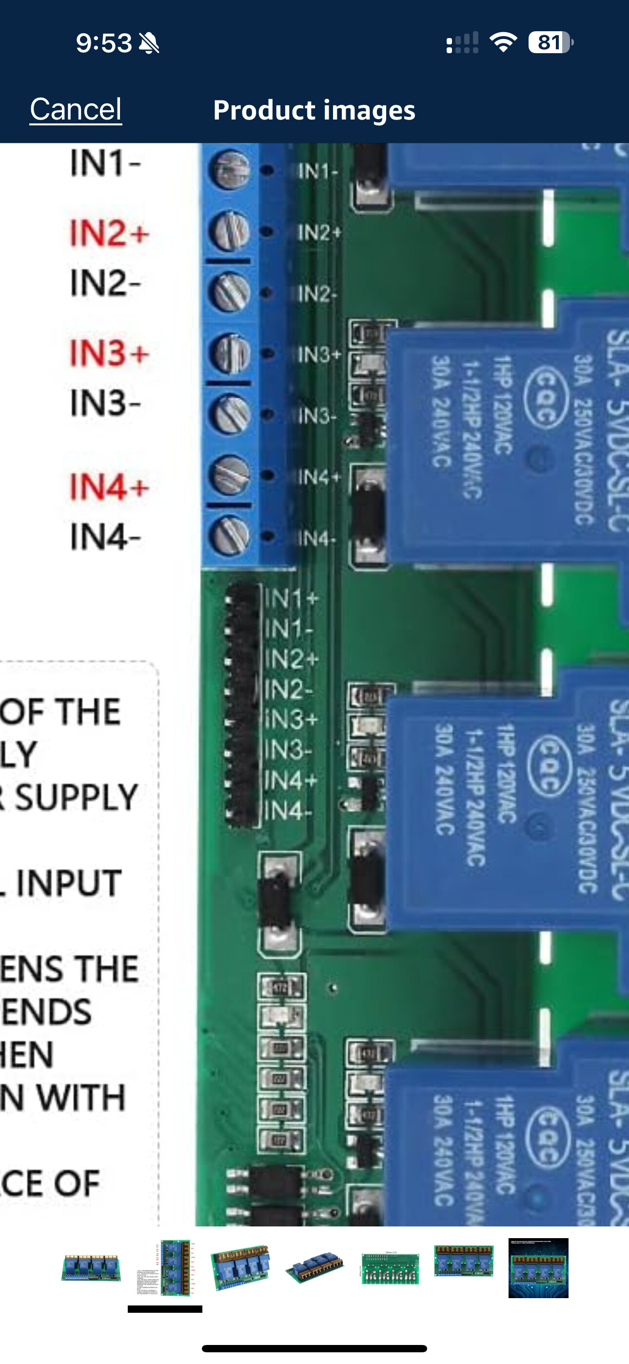
It's optocoupled relay module, you power the relay coil separately from DC +/-pins.
Int+ and int- are for arduino pins to trigger relay.
If you trigger it with output high, int- to GND and int+ to trigger pin.
Less a link to exactly what you have my best guess is on your last relay board/module all the commons were tied as a single common/ground. This board fans out the commons so each relay has a + and - control input. If you have an ohmmeter see if the negative inputs are common to each other? Purely a guess on my part less a link. ![]()
Ron
This topic was automatically closed 180 days after the last reply. New replies are no longer allowed.