I'm sure there's probably a post floating around here somewhere about this, but I can't find one that explains it well enough for my application. I also like pictures, so I've found one for my reference.
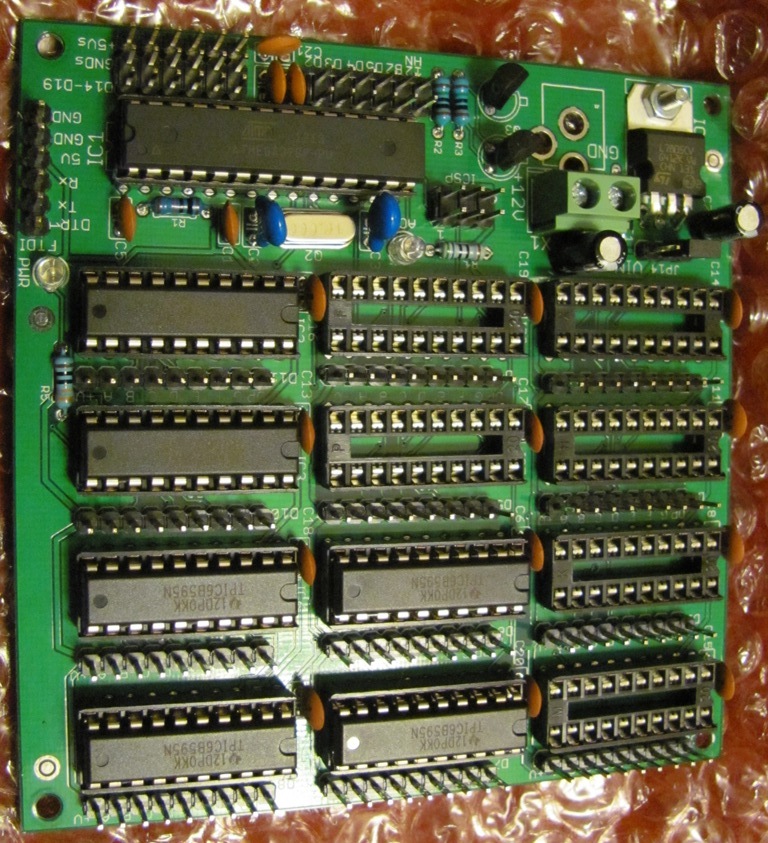
I want to design a board that will take in either a bluetooth signal or a wired (Leaning towards incorporating both depending on user preference when my whole project is done) and based on the A.I. output up to 8 PWM signals to 8 Meanwell LDD LED drivers. The idea was to just use a Atmega328P micro controller of which I have two instead of using a whole Arduino. I'd be making my own PCB with this. Before I print something however, I want to start testing the functionality, first of which is setting up a USB connection in order to program the Atmega. I found the attached picture.
Something tells me I should be connecting the USB to the RX and TX pins, but I wanted a second opinion and being new to programming a standalone Atmega, once I get the USB port in, is it just like programming a normal Arduino board?
Weird, it was suppose to be an image link to another website. Hopefully you can see the attachment. Let me know if there are any other issues.
Yes, I was planning on making the last two pins software PWM. The only other thing I plan on adding is possibly a RTC so I think it should be able to handle everything. To ultimate goal is a simple Aquarium light controller to dim lights up in the morning and down at night. The bluetooth/wired connection will be linking it to another controller that monitors the tank as a whole.
USB is a complex interface that requires negotiating between the host & slave over essentially a fancy twisted pair interface - data is simplex, and very high speed (think RS485 over twisted pair; master transmits, then the slave transmits).
Atmega34U4 (Leonardo, Micro) has USB interface built to support that. Atmega328P does not.
Yea, USB is surprisingly a little devil deep down...
Here I was thinking the Atmega328P would be simpler. I guess I'll look into some other options. A FTDI chip was going to be my next go-to though I'm thinking more of just using a Arduion Micro and making a mount on my board for it. I don't think I'm skilled enough yet to start trying to solder SMDs as those seem to be the only style accessible to me for these chips.
I use these modules to add USB to my designs as the small pitch is also beyond what I can place & solder:
Couple of examples, a 1284P board I offer (module is socketed in both pictures), and a card I wirewrapped up, and a third where I just have header pins for off-board FTDI Basic to plug onto: http://www.crossroadsfencing.com/BobuinoRev17/
first of which is setting up a USB connection in order to program the Atmega. I found the attached picture.
The picture you attached shows the connections used to implement "VUSB", which is a hack that implements low-speed USB entirely in software on an AVR that doesn't otherwise support USB protocols. You should know:
This is NOT the way that Arduinos usually use to talk to PCs over USB; most arduinos (Uno, MEGA) use a separate chip and associated components that convert the USB connection to a serial connection (which then connects to RX/TX pins of the AVR.)
The modules CrossRoads is talking about include a similar chip and components, so that they have USB in one side and RX/TX out the other (as do "FTDI Cables.")
Other Arduinos (Leonardo) have an AVR chip (32u4) that includes a special USB peripheral interface that does a lot of the USB protocol automagically.
The VUSB connection will usually NOT allow you to "program the Atmega chip." It's possible that you could write a bootloader that includes VUSB and get Arduino-like "upload" capability (Trinket, Gemma, and digispark, do this.) But you'd still need some other mechanism for programming that bootloader onto the atmega328.
If your end project will include communications with a PC over a USB cable, you should probably investigate USB/Serial modules and chips. If you only need the USB connection for initially uploading the sketch (and will speak bluetooth thereafter), you might lean more toward a cable or "device programmer" that can be shared among multiple boards (and could be an existing Arduino board.)
If you have a working prototype and are sure that your sketch will work and won't be needing serial to debug or otherwise communicate, you can get away with just putting a 3x2 ICSP header on your board, and using another Arduino or a USBTinyISP to program your board.
If you do have need for serial, then I suggest you look into the FTDI serial breakout board by Sparkfun. It contains an FTDI chip to convert USB to serial and provides six header holes. You just put in a matching set of holes on your board and now you can talk to it/program it just like a regular Arduino. The DTR pin should be connected to RST on the ATMega through a capacitor pulled up to VCC to enable auto reset. Unless you are using chips with a preloaded bootloader, you will also want an ICSP header to get the bootloader on there.
You can check out the schematic at GitHub - jinschoi/parking for an example of both (just the central section, with the chip and J1/J2). I reproduce it below.