I cut my nichrome wire to a very specific length while assuming that the ceramic terminal, the wiring and the relay would only cause a negligible amount of resistance. But after assembling the thing I noticed a massive amount of resistance across the output terminals of my SSR (2.13Kohms according to my multimeter). I found the a very similar resistance on the backup SSR I bought (2.44kohms) and a noticeable amount of resistance across the input pins (138Ohms).
As I'm very new to SSR's and AC power as a whole, I thought I'd check in to see if this is something to be expected from an SSR or if perhaps mine may be faulty.
Thanks
Edit: I realized I didn't mention that the nichrome wire IS heating up. It's just not hitting the temperatures I'd like to see with the current running through the system.
I think just knowing my DVM cant properly measure the SSR is enough to justify me leaving things where they are. I definitely do not feel confident measuring the system while it's live.
I would just like to emphases this point, the fact that you thought you could tells me you are not ready yet to work with mains voltage. You need to know a lot more about electronics first.
If you are not a achieving the temperature you want then you have calculated the wire length incorrectly. There is a lot more to it than just calculating a resistance and hence the wattage of your heater. You need to know other things like the thermal capacity of what you are trying to heat up, and the thermal resistance between that and your heater and between the heated object and ambient temperature.
This is like a heat sink calculation where you can calculate the temperature increase knowing the power and the relevant thermal resistances. However in a heat sink calculation these thermal resistances come from the data sheet. In your case you will have to measure them by putting the temperature you measure and the power of the heater into the calculation. Then you can plan what power wattage you need and then you can calculate the correct wire resistance.
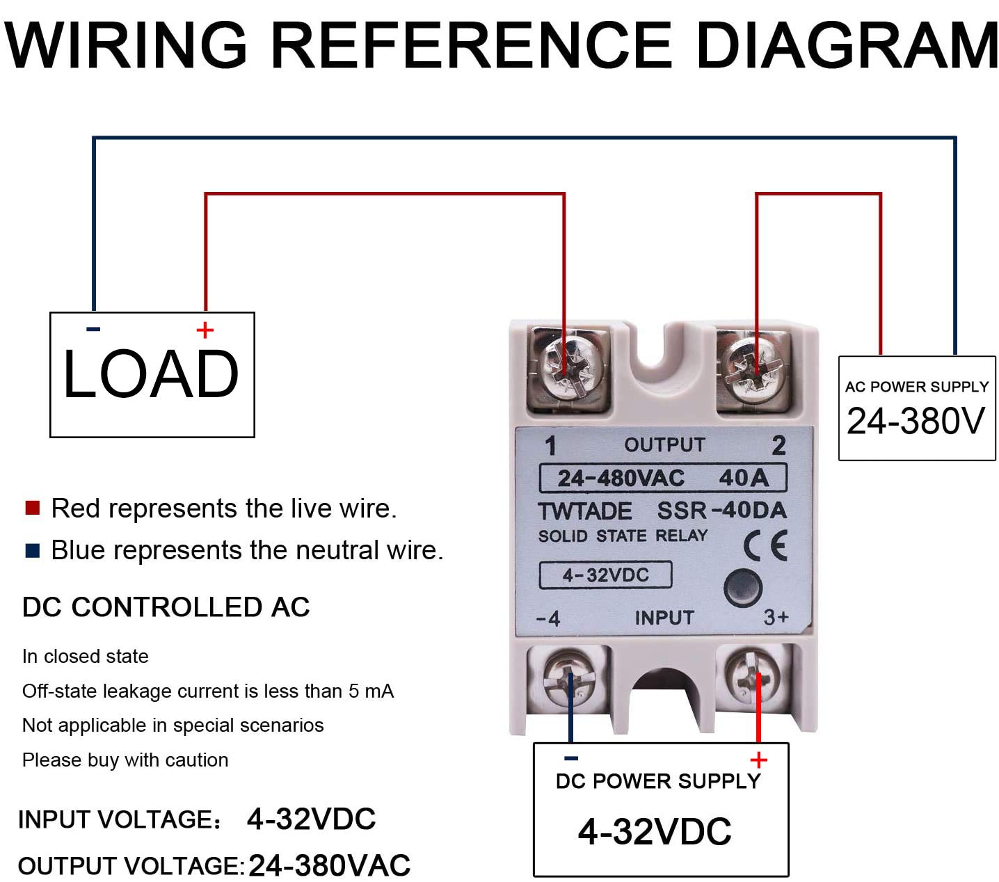
There is nothing wrong with that diagram, so nothing to apologise for, it was fine.
Put an AC current meter in series with the heating element.
I am using a similar SSR (but with a 3-32V input). When ON there is a 1.6V drop across the SSR switch so with say 10A the SSR package will get hot, (16W) and will need a heatsink
See my project on SMS hotwater control.
Currently writing up a similar project controlling a room heater via SSR
If you are uncomfortable measuring a live circuit the you might just assume the SSR is working and concentrate on the nichrome wire. Perhaps you can add additional nichrome in parallel with the existing.
If you really want to verify the SSR operation I would:
Get a set of DVM leads with alligator clips.
Add a piece of wire to SSR 1 and SSR 2 (maybe a foot)
Tape the wires to the bench so they don't move
connect the DVM to the wires
Keep you hands away from the wires and turn power on.
Just a note on the SSR resistance measurement. When not powered with AC (put with control signal) the output device will not appear to be on until you have at least 0.6 to 0.7 volts across the device. So a DVM will think it is mostly open.
Just got back into work this morning and noticed all of your responses. Thank you all
In the end I took the advice from LarryD and Grumpy_Mike and had a conversation about safety with my foreman.
We're going to put the vacformer on hold until we can get someone in who is qualified to work with mains voltage. No one working here is really qualified to do so and we want this machine to be as safe as possible for everyone in our shop.
I appreciate the safety check, and the helpful solutions that followed from everyone else!
For starters, you didn't state the operating current of the wire.
You need to connect a DMM in AC current mode in series with the wire
and connect the wire to an AC outlet with the meter in series.
Read the current and THEN and ONLY THEN can you select the properly
rated SSR for your application. Measuring the wire resistance is useless
because the resistance is a function of temperature which changes rapidly
when power is applied. If the current measured is 8A, you can use a 10A
relay. If it is 10A , you should probably choose a 15 to 20A SSR.