I bought several Arduino Zero boards and they all behave the same.
The charge indicator LED (DL2) is constantly lit when the board is powered from the USB, regardless of whether the battery is connected or not. It seems that I am not the only one who has encountered this.
What is even stranger is that when the battery is connected, it does not charge, but on the contrary, the current consumed from it (in my case, it is about 120 mA) does, despite the fact that the power from the USB is maintained (the DL1 LED is on). The battery voltage is 4.1 V, and the voltage supplied from the USB is 4.9 V. If the USB is disconnected, the consumption from the battery remains the same. Without the battery, however, the board works and the sketch is successfully executed. The battery polarity has been checked and is correct. Its capacity is more than 2000 mAh. If I connect a supercapacitor instead of a battery, it will only charge to 0.3 V.
And I didn't find any reports about such a situation on the Internet. Am I the only one who was "lucky" and all my boards are faulty in terms of the charger circuit? Or am I doing something wrong?
Addition: the charging chip is definitely sucking current from the battery. The voltage on the Vbat pin is only 0.3V. Almost all the battery voltage is applied to the F1 fuse, heating it up.
I don't think the code matters in any way. It's a hardware issue. Even the board out of the box, before programming, behaves the same way.
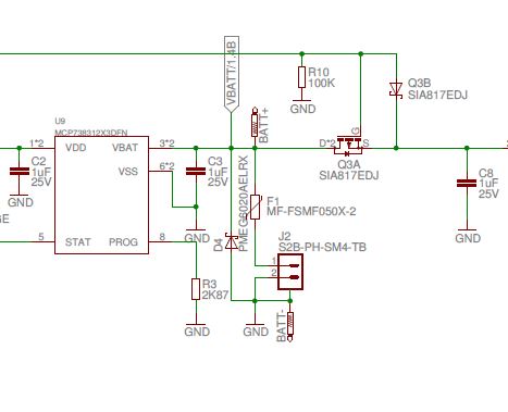
As for the wiring diagram, everyone who has dealt with the MKR Zero has one. Here is the relevant part: Clipboard_06-23-2025_01.pdf (168,3 КБ)
Thanks for the reply. I read that post and it said, among other things:
and because of reversed polarity Arduino protection stops it from powering the board.
Which is absolutely true if you look at the diagram: parallel diode D4 simply will not allow reverse voltage to be applied to the chip.
But I checked the polarity several times, and even if I made a mistake, it would be once, not all four, given the number of boards I have.
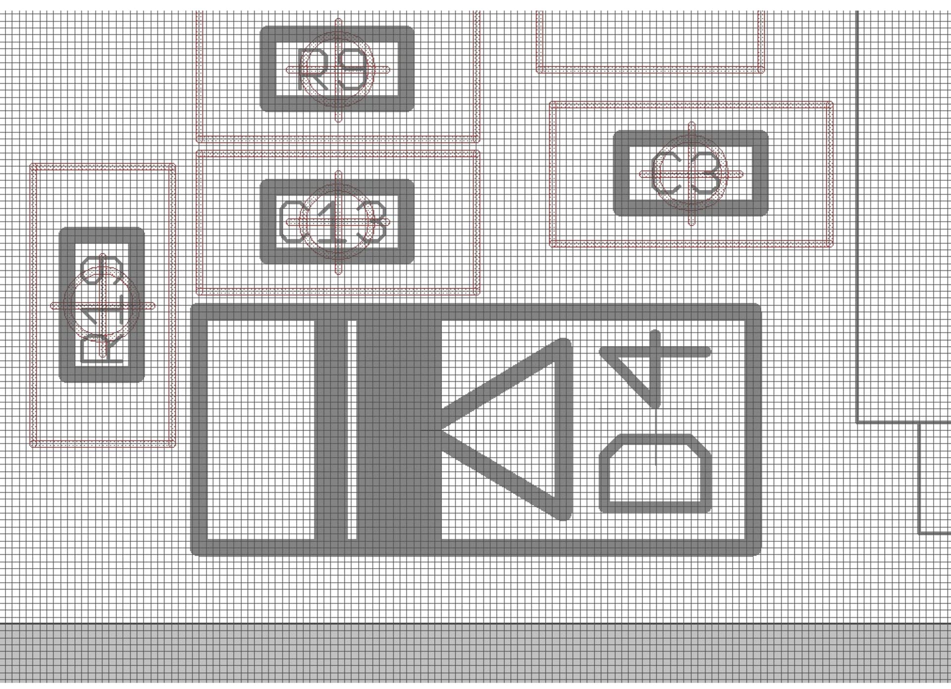
Assuming that the diode is not open or shorted and is installed with the correct polarity. Check the diode using your multimeter (battery disconnected, of course).
You know, your advice came in very handy. On all boards this diode was soldered in the opposite direction. It never even occurred to me to assume such a possibility.
By the way, all the boards were bought on Mouser.