I am trying to write a value as output using 1 pin and read it using another pin:
1 - I write 3.0V, using pin 9 (PWM). When I read it using an external voltmeter, I get 3,0V, so it is OK.
2 - I connect pin 9 to Pin A0 (Grounds are connected too). If I read it using an external voltmeter, I get 3,0V, oK!
3 - When I try to read the value of pin A0 with arduino, the value is zero or 4.88V.
LeoR7:
I am trying to write a value as output using 1 pin and read it using another pin:
1 - I write 3.0V, using pin 9 (PWM). When I read it using an external voltmeter, I get 3,0V, so it is OK.
2 - I connect pin 9 to Pin A0 (Grounds are connected too). If I read it using an external voltmeter, I get 3,0V, oK!
3 - When I try to read the value of pin A0 with arduino, the value is zero or 4.88V.
What is Wrong?
Leo.
Nothing is wrong. The external voltmeter is seeing the average voltage of the PWM.
The analogue pin is seeing either the high or low of the PWM waveform, without any smoothing/averaging.
LeoR7:
I see... So, what is the frequency of this output? How can I read the raw data?
The frequency for PWM on pin 9 is 490Hz.
By raw data, do you mean the duty-cycle?
You could use an RC filter, then measure it as an analogue voltage. That would still have some ripple on it though, unless you used a fair-sized capacitor.
Otherwise, you'd need to do it by measuring pulse-lengths.
What I want to do is very simple:
I want to write an output of variable voltage like Vout = 2+2 Sin(.5 t), where t is the time, so I have a sinusoidal signal.
At the same time, I want to read this sign using a different pin, so I can compare what is in and what is out. This is just for testing, as I am a beginner.
I have the output in pin 9 and the input in pin A0.
By the way, I am using Mathematica to read and write.
LeoR7:
What I want to do is very simple:
I want to write an output of variable voltage like Vout = 2+2 Sin(.5 t), where t is the time, so I have a sinusoidal signal.
At the same time, I want to read this sign using a different pin, so I can compare what is in and what is out. This is just for testing, as I am a beginner.
I have the output in pin 9 and the input in pin A0.
By the way, I am using Mathematica to read and write.
That's an Arduino, using an RC filter with a 10K resistor and 4.7uF cap.
If you only want a crude sine-wave, you can do it directly with an Arduino. I thought you might have wanted a reasonable quality audio frequency sine-wave.
You'd get reasonably good results by controlling a 10-bit DAC with an Arduino.
10k resistor between the PWM pin and the anaolgue pin, and a 4.7uF (or 10uF) cap from A0 to ground.
The RC filter smooths digital PWM to an analogue voltage that the A/D converter can read.
Leo..
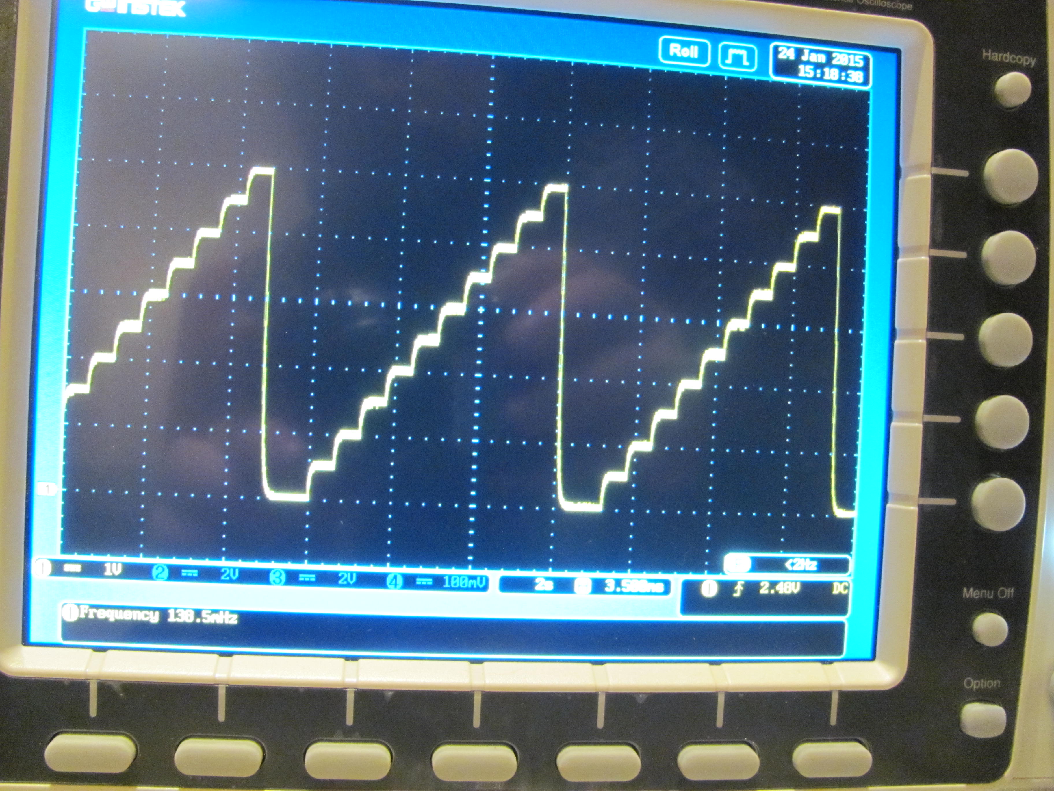
Great!! I could read it satisfactorily!! Take a look at picture.
Issues:
There is a shift in voltage value. My output is set to 1.50V, but the reading is 1.465V using Arduino or a Voltmeter. Is it expected?
In the picture, we see the filter with one 22uF capacitor and other filter with 47uF capacitor. What is the limit for the capacitor? Should I use a bigger one and have "zero noise"?
You can never get to zero noise. A bigger capacitor will reduce the ripple but the tradeoff is that it will be slower to change to the next voltage. See the picture posted earlier. That's an extremely slow waveform but you can still see the transitions aren't instant - it takes a little while to get to the next value.
There is a shift in voltage value. My output is set to 1.50V, but the reading is 1.465V using Arduino or a Voltmeter. Is it expected?
In the picture, we see the filter with one 22uF capacitor and other filter with 47uF capacitor. What is the limit for the capacitor? Should I use a bigger one and have "zero noise"?
8-bit PWM = 256 steps. Every step is 1/256 of the supply voltage. ~19.5mV per step on a 5volt Arduino.
Supply could be 5volt, but it could also be 4.75volt or 5.25volt (is within specs of the onboard regulator).
USB supply could be worse. Supply could also have some hash on it.
No limit. Settle time will increase with larger value caps.
A two-stage filter can be used. R-C-R-C
Leo..