Hello everyone
I am trying to read the voltage in a pwm pin as I see in my multimeter I would like to show this value in an lcd but I can not, I tried through calculations but the values are not accurate.
Hello everyone
I am trying to read the voltage in a pwm pin as I see in my multimeter I would like to show this value in an lcd but I can not, I tried through calculations but the values are not accurate.
The value will be close to Vcc or close to zero.
Helo Delta_g
Can you help me with this circuit?
I am trying to read the voltage in a pwm pin
Do you mean a PWM output or an analogue input pin ?
Can you please give an example of the pin number that you are using and the board type ?
(deleted)
rrsilver:
I am trying to read the voltage in a pwm pin
Why ? You can calculate it easily.
Suppose you use analogWrite(pin, 63); then the average voltage will be 5 * 63 / 255 = 1.235
...R
UKHeliBob:
Do you mean a PWM output or an analogue input pin ?used pin 8
Can you please give an example of the pin number that you are using and the board type ?
arduino mega
this value in the multimeter is the current value of pin 8 I just wanted to show on an equal lcd is in the multimeter, I tried to understand the low pass filter but I am not understanding the results I found in google.
rrsilver:
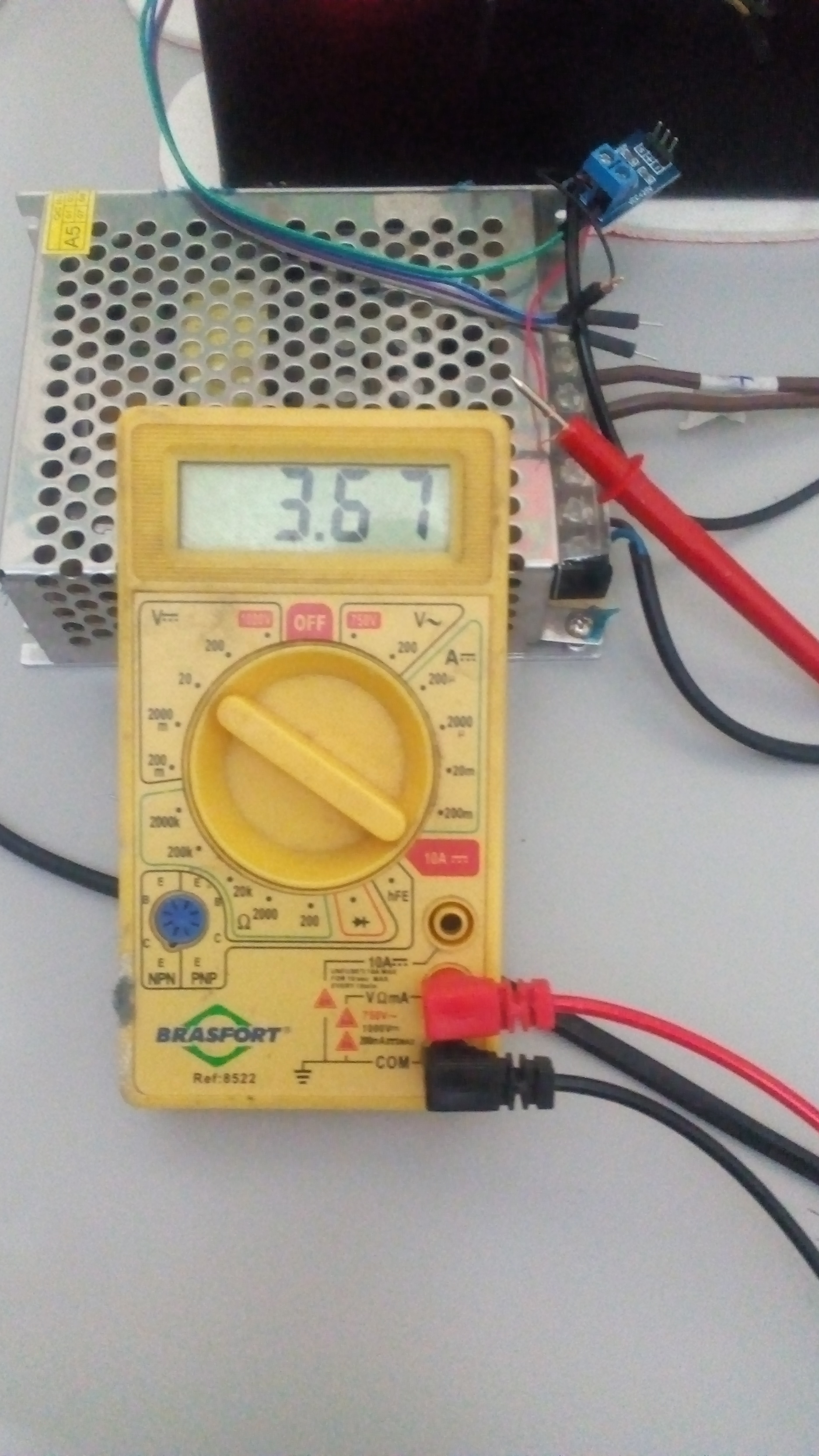
I am trying to read the voltage in a pwm pin as I see in my multimeter
I would like to show this value in an lcd but I can not,
I tried through calculations but the values are not accurate.
We did't see your calculation, but the right calculation is given in post#6.
AnalogWrite is not generating a voltage, but a square wave signal (0volt, 5volt), with varying on/off time.
Your multimeter will average that 5volt PWM signal, but it might not do that very accurately.
Tell us why you need a 'voltage'.
Leo..
the value will be handled by a person but only once it will be configured and shown in real time on an lcd after that it will be retained, I made a calculation but it is not accurate and shows only rounded values
I have this code but it's not accurate
double Vcc = 5.0; // not necessarily true
    double volt = (final_voltsO2 / 255.0) * Vcc; // only correct if Vcc = 5.0 volts
    Serial.println(volt);
Wawa:
We did't see your calculation, but the right calculation is given in post#6.AnalogWrite is not generating a voltage, but a square wave signal (0volt, 5volt), with varying on/off time.
Your multimeter will average that 5volt PWM signal, but it might not do that very accurately.
Tell us why you need a 'voltage'.
Leo..
I need to fool an automotive sensor but I must give this freedom to change the voltage to the user and he can see it on an lcd to know what he is doing.
Robin2:
Why ? You can calculate it easily.Suppose you use analogWrite(pin, 63); then the average voltage will be 5 * 63 / 255 = 1.235
...R
I am using this code but it is not accurate and brings rounded results by ignoring the decimal places.
my code
analogWrite(8, 102); // OBS: 102 value is the int var final_voltsO2
    double Vcc = 5.0; // not necessarily true
    double volt = (final_voltsO2 / 255.0) * Vcc; // only correct if Vcc = 5.0 volts
    Serial.println(volt);
serial result is 2.00 volt in my multimeter now the value is 1.83 volts
final_voltsO2 = map(vlr_eprom_lambda, 0, 5, 0, 255);
this variable is used for the map value when user change values in lcd control
rrsilver:
I am using this code but it is not accurate and brings rounded results by ignoring the decimal places.
Simply change the int assignment to a float, then do 100*(5*60)/255 analogWrite(pin, 60);
Then when looking at the lcd screen the move the decimal place 2 places back or edit when printing the final str to the LCD.
rrsilver:
final_voltsO2 = map(vlr_eprom_lambda, 0, 5, 0, 255);
map() only works with integers.
That line only outputs five voltage levels (steps of one volt).
Leo..
I just wanted to show the same value that is shown in the multimeter on my lcd screen but it is very difficult for me, I did a lot of research and I do not think how to do that.
I'm posting a video on youtube to see if it's easier for you to give me a tip
rrsilver:
Hello everyoneI am trying to read the voltage in a pwm pin as I see in my multimeter I would like to show this value in an lcd but I can not, I tried through calculations but the values are not accurate.
The 'time-averaged' voltage over 1 single PWM period can be calculated in advance ---- as long as you know the peak DC voltage level...eg. 5V (or whatever it is).
But we also go to keep certain situations in mind ....... such as.... the difference between 50% PWM duty cycle for a PWM waveform having a period of 1 millisecond, versus 50% PWM duty cycle for a PWM waveform having a period of 10 seconds.
the sensor is a lambda probe that should send the ECU a value between 600 and 900 millivolts
Delta_G:
Have you checked your reference voltage? Is it EXACTLY 5.0 volts? If not you need to use the actual value and not 5.0Depending on the board you have there may be 1 or 2 internal voltage references. The 1.1V reference is usually pretty good and stable and accurate.
You also need to understand that your multimeter is not going to measure a PWM signal like it would a steady voltage. Right now your voltage is flickering back and forth from 0 to 5V really fast. IF your multimeter does anything other than flicker back and forth between 0 and 5V so fast you can't see it then the multimeter is lying to you. You are NOT creating 1.83 OR 2.00 volts. Only 0 and 5 volts.
While you are correct about creating 0 and 5 volts, It happens so fast that the voltage is effectively 2. Also adding an electrolytic capacitor with a fairly large capacity ex 470uf(common) between the PWM Pin and ground will smooth the voltage if there is a load. Without a load the capacitor will just charge to 5v. This then can be measured with a multimeter.