I ll use 4x2.5m ws2812b Led. Using 5v10a powercase.I ll connect + - led connections to power case and din to arduino pins for 4 leds. On the photo it make second gnd connection to arduino on the same black cable to led gnd.should i do that and if i dont will anything happen? Shortly can i control my led ony make 3(+-,din) connections.
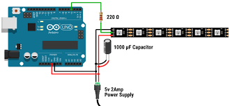
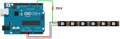
It is important that the Arduino and the LED strip share a common GND connection in order that there is a common pint of reference for the voltage level of the data signal from the Arduino. If you don't have such a common GND connection then the LEDs will not behave as you want or expect
Your diagram seems to show such a connection and is, therefore correct
i want to do like this cause this is basic and will not be that much cable on the box. It ll seen more organised. Thats why but i ll not use 6led as the photo i ll use 75led so thats why i ask
Ok so must do the what u shared before right. I asked it but ll write down again can i make it with breadboard right that arduino led gnd connections and led powersupply connection. I think i ll be more organised right?
Be very wary of using a breadboard due to the amount of current being used. You have 300 LEDs, each of which will take about 60mA when set to white at full brightness. That is a potential total current of 18A. If that much current passes through a breadboard then it will melt
I am sure that you are going to tell me that all 300 LEDs will never be full on white, but accidents happen
If the power to the LEDs does not go through the breadboard then you will be OK to use one as the control signal uses very little current
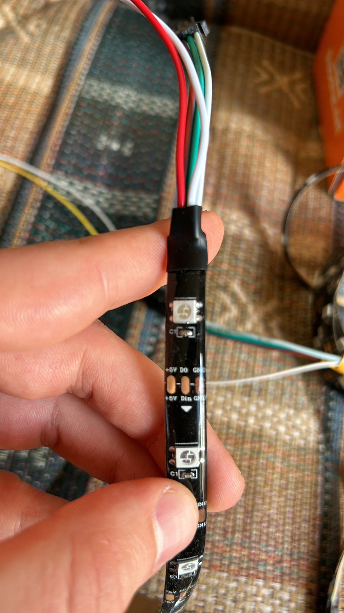
These are my leds connections. i ll use the black arrow for the +-din connections and white cables with the pink arrow is fot the second gnd connections to the arduino so if i wrap these 2 white cables and using the jumper to put it in the arduino gnd as one output is this problem?
The current provided by a 5V power source needs to flow back to that 5V power source.
The signal provided by the Arduino needs to flow back to the Arduino.
Notes:
You need a decent 5V power supply; 300 pixels times 60 mA equals 18 A; add a bit of headroom and you end with a 20 A power supply.
300 pixels require 900 bytes of RAM if you want to be able to control each pixel individually; that is nearly 50% of the memory of the Uno that you have shown in your image. Depending on the complexity of the sketch, you might run out of memory on the Uno.
You are over complicating this. Both reds are connected together and both whites are connected together on the strip.
So one white to arduino GND and another white to PSU negative. One red to PSU positive. Green to arduino signal pin. If you want to power arduino from that same PSU, other red to arduino 5V pin. No need to wrap or jumpers.
They have that kind of wiring, because just with that din connector you can have a working circuit with controller. If you need to provide more power (like your case) you use those other two wires for additional PSU.
ps. if you want to connect to arduino with jumper cables, they usually fit well in that black connector pins.