WS2812B and Arduino Nano RP2040

Hi,

This is my first project, and post on this forum.
I started an infinity LED cube project, using an Arduino to control a WS2812B LED strip.

I ordered the Arduino Nano RP2040 in case I want to expand my project later and make it controllable via BLE, or even the network, but for now I am just looking at getting the LEDs to light up, which I have been...completely failing at :stuck_out_tongue:

I tried following a few different learning sources and tutorials, including this one, which was very clear and simple, with no luck.

I then found out that the 5V pin on the RP2040 was not available unless you soldered both VUSB pins, which I did, without any positive impact.

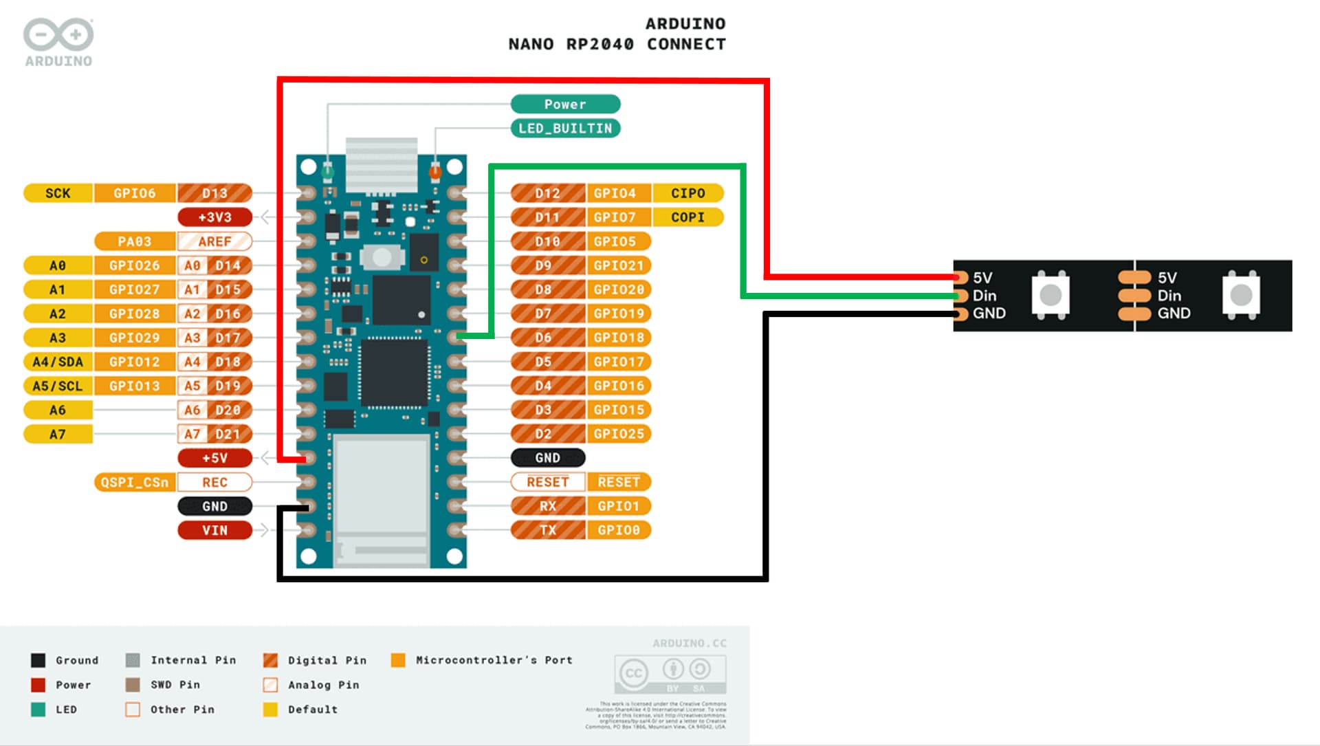
Here is a diagram of my wiring:

And here is the code I am uploading using the Arduino IDE:

#include <FastLED.h>

FASTLED_USING_NAMESPACE

#define DATA_PIN 6
#define LED_TYPE WS2812B
#define COLOR_ORDER GRB
#define NUM_LEDS 144
CRGB leds[NUM_LEDS];

#define BRIGHTNESS 96
#define FRAMES_PER_SECOND 120

#define VOLTS 5
#define MAX_AMPS 500

void setup() {
  delay(3000);  // 3 second delay for recovery

  // tell FastLED about the LED strip configuration
  FastLED.addLeds<LED_TYPE, DATA_PIN, COLOR_ORDER>(leds, NUM_LEDS).setCorrection(TypicalLEDStrip);
  //FastLED.addLeds<LED_TYPE,DATA_PIN,CLK_PIN,COLOR_ORDER>(leds, NUM_LEDS).setCorrection(TypicalLEDStrip);
  FastLED.setMaxPowerInVoltsAndMilliamps(VOLTS, MAX_AMPS);
  // set master brightness control
  FastLED.setBrightness(BRIGHTNESS);
  FastLED.clear();
  FastLED.show();
}

void loop() {

  leds[0] = CRGB(255, 0, 0);
  FastLED.show();
  delay(100);
}

For now, I am only trying to get 1 LED to light up, so I assumed it would be fine powering it through the Arduino USB, but I cannot get it to work.

A list of the things I have tried:

  • Using the VIN pin instead of the 5V pin -> no change
  • Using/Not using a breadboard for my connections -> no change
  • Measuring the voltage out of the Arduino -> I get 5V
  • Powering the LED strip using an external power source (Positive and GND wires connected to the +/- of the 5V-10A power adapter respectively) -> no change
  • Trying with a different LED strip -> no change
  • Using a different Data Pin -> no change

I am a bit at a loss here, hoping somebody who has experienced the same issue, or simply with more knowledge, can help me :slight_smile:

Thank you!

This may be a dumb question but are you connected to the input-end of the LED strip?

Not sure this is what you are asking for but I made sure the arrows on the LED strip were pointing away from the Arduino, and not towards it.

Those are in milliamps, not amps (you hope).

Try a minimal sketch (blink LED zero).

#include <FastLED.h>
#define DATA_PIN 6
#define NUM_LEDS 60
CRGB leds[NUM_LEDS];
void setup() { FastLED.addLeds<NEOPIXEL, DATA_PIN>(leds, NUM_LEDS); }
void loop() {
    leds[0] = CRGB::White; FastLED.show(); delay(30); // all LEDs on
    leds[0] = CRGB::Black; FastLED.show(); delay(30); // all LEDs off also FastLED.clear(); 
}

You better power LED strip via external power with a capacitor and resistor as below image:

You can also try the NeoPixel Library from Adafruit. More detail instruction is available in this Arduino Nano WS2812B LED strip tutorial

Those are mA indeed, I will update the description to make it clearer!
Simple code did not yield better results :confused:

I don't have a capacitor yet, just ordered it, but I tried my my external power adapter, and a 10k Ohm resistor, following the same wiring, still no result.
I will try again with the capacitor when it gets here, but my understanding is that I should be able to power it via the USB, shouldn't I?

I do read 5V on my multimeter on the VUSB pin.

Anyways thank you for even answering, I really appreciate the help ^^

Verify the pin you are referencing is correct. Do a blink sketch with an LED and resistor.

Hi @qsylvestre. There is a tricky thing about the FastLED library: It uses the low level GPIO numbers of the RP2040 microcontroller instead of the Arduino pin numbers. You can see from the pinout diagram you shared that Arduino pin number 6 is GPIO number 18:

image

so you should change this line of your sketch:

to this:


Another thing I'll add: is that the WS2812B is actually intended to be used with 5 V logic levels instead of the 3.3 V of the Nano RP2040 Connect board. I verified that it does work with your wiring, but if you run into troubles you could try powering the WS2812B with 3.3 V instead of 5 V. In the past when I had problems with reliability in project using these addressable LEDs I found this solved it even though powering the LEDs at 3.3 V is technically out of spec.

The best practices configuration would be to power the WS2812B at 5 V and use a level converter to change the data signal from the Nano RP2040 Connect to 5 V, but that makes the circuit more complex.

1 Like

Hi all, quick update out of respect for everyone who was kind enough to answer:

When I was trying to power the LEDs using an external 5V/10A power adapter, I fried my Arduino (I had exposed 2 cables of my LED strip previously, and they were touching when I plugged everything in... :man_facepalming:).

Anyways, I have a new Arduino (regular 5V Nano this time), capacitors and resistors now, and my setup worked first go using the same wiring!

I would still like to understand the issue, though, because I thought I was powering the LEDs using the 5V output of the Arduino (measured using a multimeter??). After seeing @ptillisch answer, it could be it, I don't think I had the time to check using data pin 18 before frying my RP2040...

Anyways, I'm glad it works now, thanks for your help!

I will post here if I end up trying again on a RP2040, just to log the resolution :slight_smile:

This topic was automatically closed 180 days after the last reply. New replies are no longer allowed.