Hey guys,
Trying to have a WS2812B strip , do the blink test.
In my setup, i have 20 leds, however only focusing on 1 led to blink correctly.
The colors displayed are incorrect. When I call for red, green is displayed, and vice versa.
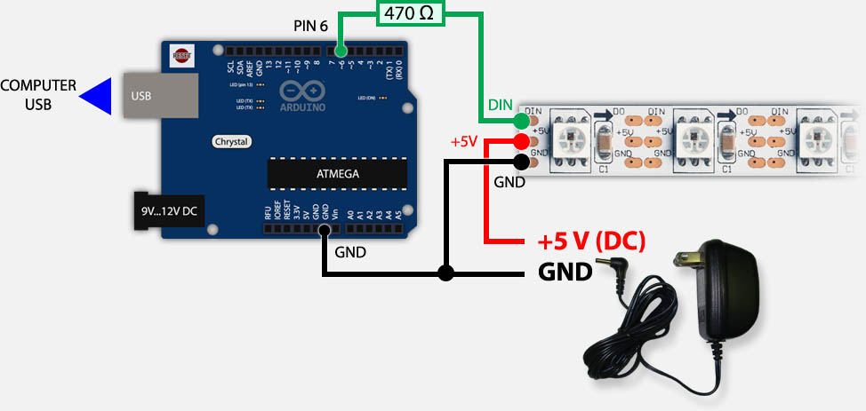
My wiring consist of having the Uno powered via USB, and the LEDs are powered with an external 5v power supply.
From power supply, I use a 1000uf capacitor.
From the power supply, negative side connect to ground terminal on the Uno.
From the power supply, negative and positive to the WS2812B terminals.
From data pin3, a 330-ohm resistor, then the WS2812B data in line.
To my understanding so far, i have followed the diagrams floating around like the one in tweaking for all, except i use a 1000uf capacitor at the output of the transformer and a 330 resistor instead of the 470 in the diagram.
Very new to this, and understanding that having the ground side of the electronics is crucial for communication. Which is my next question, why does the WS2812B act erratic when the ground line is disconnected? ::flame suit::
I looked at CRGB and not sure how to change it. Thanks again.
I also understand that the WS2812B does not need a clock_pin
// How many leds in your strip?
#define NUM_LEDS 1

// For led chips like Neopixels, which have a data line, ground, and power, you just
// need to define DATA_PIN.  For led chipsets that are SPI based (four wires - data, clock,
// ground, and power), like the LPD8806 define both DATA_PIN and CLOCK_PIN
#define DATA_PIN 3
#define CLOCK_PIN 13
#define COLOR_ORDER BGR
// Define the array of leds
CRGB leds[NUM_LEDS];

void setup() {
      // Uncomment/edit one of the following lines for your leds arrangement.
      // FastLED.addLeds<TM1803, DATA_PIN, RGB>(leds, NUM_LEDS);
      // FastLED.addLeds<TM1804, DATA_PIN, RGB>(leds, NUM_LEDS);
      // FastLED.addLeds<TM1809, DATA_PIN, RGB>(leds, NUM_LEDS);
      // FastLED.addLeds<WS2811, DATA_PIN, RGB>(leds, NUM_LEDS);
      // FastLED.addLeds<WS2812, DATA_PIN, RGB>(leds, NUM_LEDS);
      FastLED.addLeds<WS2812B, DATA_PIN, RGB>(leds, NUM_LEDS);
  	  // FastLED.addLeds<NEOPIXEL, DATA_PIN>(leds, NUM_LEDS);
      // FastLED.addLeds<APA104, DATA_PIN, RGB>(leds, NUM_LEDS);
      // FastLED.addLeds<UCS1903, DATA_PIN, RGB>(leds, NUM_LEDS);
      // FastLED.addLeds<UCS1903B, DATA_PIN, RGB>(leds, NUM_LEDS);
      // FastLED.addLeds<GW6205, DATA_PIN, RGB>(leds, NUM_LEDS);
      // FastLED.addLeds<GW6205_400, DATA_PIN, RGB>(leds, NUM_LEDS);

      // FastLED.addLeds<WS2801, RGB>(leds, NUM_LEDS);
      // FastLED.addLeds<SM16716, RGB>(leds, NUM_LEDS);
      // FastLED.addLeds<LPD8806, RGB>(leds, NUM_LEDS);
      // FastLED.addLeds<P9813, RGB>(leds, NUM_LEDS);
      // FastLED.addLeds<APA102, RGB>(leds, NUM_LEDS);
      // FastLED.addLeds<DOTSTAR, RGB>(leds, NUM_LEDS);

      // FastLED.addLeds<WS2801, DATA_PIN, CLOCK_PIN, RGB>(leds, NUM_LEDS);
      // FastLED.addLeds<SM16716, DATA_PIN, CLOCK_PIN, RGB>(leds, NUM_LEDS);
      // FastLED.addLeds<LPD8806, DATA_PIN, CLOCK_PIN, RGB>(leds, NUM_LEDS);
      // FastLED.addLeds<P9813, DATA_PIN, CLOCK_PIN, RGB>(leds, NUM_LEDS);
      // FastLED.addLeds<APA102, DATA_PIN, CLOCK_PIN, RGB>(leds, NUM_LEDS);
      // FastLED.addLeds<DOTSTAR, DATA_PIN, CLOCK_PIN, RGB>(leds, NUM_LEDS);
}

void loop() {
  // Turn the LED on, then pause
  leds[0] = CRGB::Blue;
  FastLED.show();
  delay(1000);
  // Now turn the LED off, then pause. Red Call is displaying Green. Color arrangement out of order.
  leds[0] = CRGB::Red;
  FastLED.show();
  delay(1000);

  // Testing for Green call. Green Call is displaying Red. Color arrangement out of order.
  leds[0] = CRGB::Green;
  FastLED.show();
  delay(3000);
}