#include <FastLED.h>

// How many leds in your strip?
#define NUM_LEDS 1

// For led chips like WS2812, which have a data line, ground, and power, you just
// need to define DATA_PIN.  For led chipsets that are SPI based (four wires - data, clock,
// ground, and power), like the LPD8806 define both DATA_PIN and CLOCK_PIN
// Clock pin only needed for SPI based chipsets when not using hardware SPI
#define DATA_PIN 3
#define CLOCK_PIN 13

// Define the array of leds
CRGB leds[NUM_LEDS];

void setup() {
   // Uncomment/edit one of the following lines for your leds arrangement.
   // ## Clockless types ##
   FastLED.addLeds<NEOPIXEL, DATA_PIN>(leds, NUM_LEDS);  // GRB ordering is assumed
   // FastLED.addLeds<SM16703, DATA_PIN, RGB>(leds, NUM_LEDS);
   // FastLED.addLeds<TM1829, DATA_PIN, RGB>(leds, NUM_LEDS);
   // FastLED.addLeds<TM1812, DATA_PIN, RGB>(leds, NUM_LEDS);
   // FastLED.addLeds<TM1809, DATA_PIN, RGB>(leds, NUM_LEDS);
   // FastLED.addLeds<TM1804, DATA_PIN, RGB>(leds, NUM_LEDS);
   // FastLED.addLeds<TM1803, DATA_PIN, RGB>(leds, NUM_LEDS);
   // FastLED.addLeds<UCS1903, DATA_PIN, RGB>(leds, NUM_LEDS);
   // FastLED.addLeds<UCS1903B, DATA_PIN, RGB>(leds, NUM_LEDS);
   // FastLED.addLeds<UCS1904, DATA_PIN, RGB>(leds, NUM_LEDS);
   // FastLED.addLeds<UCS2903, DATA_PIN, RGB>(leds, NUM_LEDS);
   // FastLED.addLeds<WS2812, DATA_PIN, RGB>(leds, NUM_LEDS);  // GRB ordering is typical
   // FastLED.addLeds<WS2852, DATA_PIN, RGB>(leds, NUM_LEDS);  // GRB ordering is typical
   // FastLED.addLeds<WS2812B, DATA_PIN, RGB>(leds, NUM_LEDS);  // GRB ordering is typical
   // FastLED.addLeds<GS1903, DATA_PIN, RGB>(leds, NUM_LEDS);
   // FastLED.addLeds<SK6812, DATA_PIN, RGB>(leds, NUM_LEDS);  // GRB ordering is typical
   // FastLED.addLeds<SK6822, DATA_PIN, RGB>(leds, NUM_LEDS);
   // FastLED.addLeds<APA106, DATA_PIN, RGB>(leds, NUM_LEDS);
   // FastLED.addLeds<PL9823, DATA_PIN, RGB>(leds, NUM_LEDS);
   // FastLED.addLeds<SK6822, DATA_PIN, RGB>(leds, NUM_LEDS);
   // FastLED.addLeds<WS2811, DATA_PIN, RGB>(leds, NUM_LEDS);
   // FastLED.addLeds<WS2813, DATA_PIN, RGB>(leds, NUM_LEDS);
   // FastLED.addLeds<APA104, DATA_PIN, RGB>(leds, NUM_LEDS);
   // FastLED.addLeds<WS2811_400, DATA_PIN, RGB>(leds, NUM_LEDS);
   // FastLED.addLeds<GE8822, DATA_PIN, RGB>(leds, NUM_LEDS);
   // FastLED.addLeds<GW6205, DATA_PIN, RGB>(leds, NUM_LEDS);
   // FastLED.addLeds<GW6205_400, DATA_PIN, RGB>(leds, NUM_LEDS);
   // FastLED.addLeds<LPD1886, DATA_PIN, RGB>(leds, NUM_LEDS);
   // FastLED.addLeds<LPD1886_8BIT, DATA_PIN, RGB>(leds, NUM_LEDS);
   // ## Clocked (SPI) types ##
   // FastLED.addLeds<LPD6803, DATA_PIN, CLOCK_PIN, RGB>(leds, NUM_LEDS);  // GRB ordering is typical
   // FastLED.addLeds<LPD8806, DATA_PIN, CLOCK_PIN, RGB>(leds, NUM_LEDS);  // GRB ordering is typical
   // FastLED.addLeds<WS2801, DATA_PIN, CLOCK_PIN, RGB>(leds, NUM_LEDS);
   // FastLED.addLeds<WS2803, DATA_PIN, CLOCK_PIN, RGB>(leds, NUM_LEDS);
   // FastLED.addLeds<SM16716, DATA_PIN, CLOCK_PIN, RGB>(leds, NUM_LEDS);
   // FastLED.addLeds<P9813, DATA_PIN, CLOCK_PIN, RGB>(leds, NUM_LEDS);  // BGR ordering is typical
   // FastLED.addLeds<DOTSTAR, DATA_PIN, CLOCK_PIN, RGB>(leds, NUM_LEDS);  // BGR ordering is typical
   // FastLED.addLeds<APA102, DATA_PIN, CLOCK_PIN, RGB>(leds, NUM_LEDS);  // BGR ordering is typical
   // FastLED.addLeds<SK9822, DATA_PIN, CLOCK_PIN, RGB>(leds, NUM_LEDS);  // BGR ordering is typical
}

void loop() {
 // Turn the LED on, then pause
 leds[0] = CRGB::Red;
 FastLED.show();
 delay(500);
 // Now turn the LED off, then pause
 leds[0] = CRGB::Black;
 FastLED.show();
 delay(500);
}
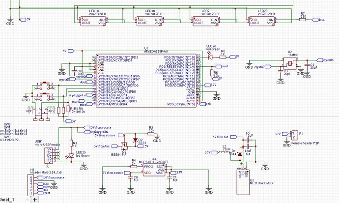
So this is the code for the FastLED blink example. Its supposed to blink the WS2812 red, but it just stays white. Its the same with all the other FastLED examples. As far as using just white WS2812, I don't think so. I got the board pre-assembled by JLCPCB, and they look like the black PCB RGB in the above post. I feel like its a software problem, but I recently tried it with AdaFruit's NeoPixel library, and still got the same thing

