Ha Ha! Both wrong again!
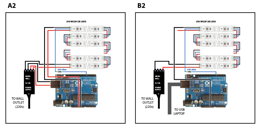
Your original diagrams were correct insofar as you need to connect the power - direct from the power supply - to at least both ends of 256 WS2812 pixels. This is of course necessary as the foils on the strips are not particularly sturdy and will lose voltage over any significant distance when carrying substantial current - 256 LEDs will be 14 Amps so now you mention it, your power supply is quite inadequate!
But you can do a lot better than that! You say a 16 by 16 matrix and you are using the "Zigzag" format where the data runs in opposite directions in alternate rows, which is the proper way to do it as it means that the data line does not have to traverse back to the "start" of each row. Your library will take that into account.
So what you actually do, is to connect 5 V and ground to every row in parallel at each end. And for only 16 LEDs per row, it will generally be sufficient to connect only one end - either end - to the power supply. Having all the strips tied together for power at the other end will mean that any one row drawing full power will be supported by the others and in any case, each 16 LED strip draws less than one Amp on its own.
So you bring the power back to the Arduino UNO (should really be a Nano, UNOs are inconvenient to use) along with the data wire from the first strip, not via the USB jack and not separately from the power supply. The important thing is to avoid any open loops in the wiring.
bijzettafel69:
Image A makes sense for me with what you are saying. The power supply supplies 10A to the USB (which is regulated).
Not sure what you mean by "which is regulated", but there are components between the USB connector and the actual 5 V supply line in the UNO - the "5V" pin - including a 500 mA "polyfuse" so supplying ia te "5V" pin is more direct. With a caveat which follows:
bijzettafel69:
Image B does not fully make sense to me still. Why should I only disconnect the 5V pin? Sorry, I am not very experienced with arduino and external power.
With power supplied to the "5V" pin, it can potentially feed back into the USB port of a connected PC and this appears to be a particular danger with laptops, it may temporarily or even permanently shut down the USB system requiring removal of the battery to (maybe) resolve. This is not certain, but a risk which has been reported, so the advice is not to connect an external supply of 5 V to the "5V" pin if you are going to connect a PC to the USB jack.
bijzettafel69:
I am not sure what you mean with ''470 µF capacitor across 5 V and ground''.
That is routinely advised to stabilise the signal at the first LED. Also the resistor.
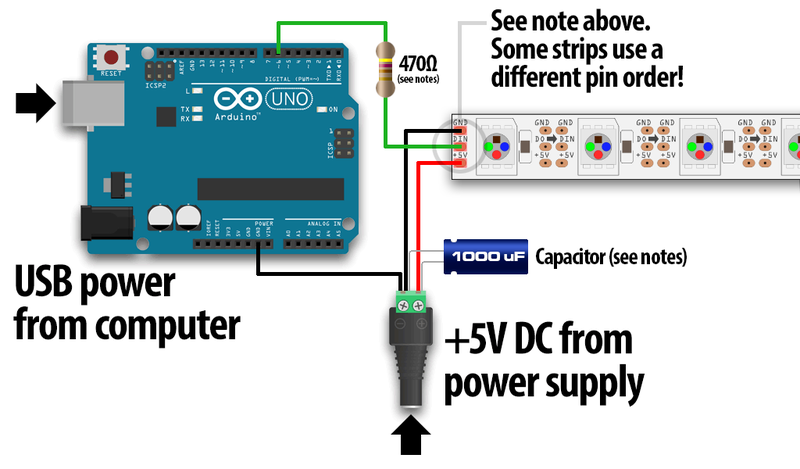
Adafruit reference.
OK, just to make it clear, this diagram is only about the location of the capacitor, nothing else!
bijzettafel69:
Should I connect a capacitor at the 5v and ground pins of the arduino? I have a 1000uF 16V capacitor, would that work? Just stick in into the pins?
Value is OK (as in the diagram, no quibble on the exact value) but it goes across the LED strip, not the Arduino.