www.mcufriend.com working in arduino uno and arduino mega

You can see that your module ribbon is soldered directly to the left hand set of pads.
I suspect that a different brand of module might use the other set of pads.

A third brand of module might have a ribbon that pokes through the cut-out slot and plugs into a ribbon socket soldered to the empty footprint that you first noticed.

If you have been gentle with unpeeling the double sided foam sticky pads, no physical damage will be caused.

I am still worried about your breadboard arrangement. LCD_D2 .. LCD_D1 have the wrong spacing for a breadboard. If you have not connected the 3.3V power pin, the display might receive 5V logic.

If you really want help, please answer:

  1. have you mated the shield?
  2. does LCD_ID_readreg work?
  3. have you installed the Beta library? (delete any old library first)
  4. what does graphictest_kbv say on the Serial Terminal?

David.

david_prentice:
If you really want help, please answer:

  1. have you mated the shield?
  2. does LCD_ID_readreg work?
  3. have you installed the Beta library? (delete any old library first)
  4. what does graphictest_kbv say on the Serial Terminal?
    David.
  1. I don't understand what mated means, I connected it a) by putting it on the Mega (3.3V goes to 3.3V 5V goes to 5V etc and b) by using breadboard cables and connect 3.3 to 3.3, 5v to 5v, ground to groung and lcd_00 to 07 to pind 22-29, also tried lcd_cs_wr etc to 38-40 and analog 0 to 3
  2. YES I posted it a few posts ago and you informed me about the model (thank you)
 Read Registers on MCUFRIEND UNO shield
controllers either read as single 16-bit
e.g. the ID is at readReg(0)
or as a sequence of 8-bit values
in special locations (first is dummy)

reg(0x0000) 00 00	ID: ILI9320, ILI9325, ILI9335, ...
reg(0x0004) 00 00 00 00	Manufacturer ID
reg(0x0009) 00 00 00 00 00	Status Register
reg(0x000A) 08 08	Get Powsr Mode
reg(0x000C) 66 66	Get Pixel Format
reg(0x0061) 00 00	RDID1 HX8347-G
reg(0x0062) 00 00	RDID2 HX8347-G
reg(0x0063) 00 00	RDID3 HX8347-G
reg(0x0064) 00 00	RDID1 HX8347-A
reg(0x0065) 00 00	RDID2 HX8347-A
reg(0x0066) 00 00	RDID3 HX8347-A
reg(0x0067) 00 00	RDID Himax HX8347-A
reg(0x0070) 00 00	Panel Himax HX8347-A
reg(0x00A1) 00 00 00 00 00	RD_DDB SSD1963
reg(0x00B0) 00 00	RGB Interface Signal Control
reg(0x00B4) 00 00	Inversion Control
reg(0x00B6) 00 00 00 00 00	Display Control
reg(0x00B7) 00 00	Entry Mode Set
reg(0x00BF) 01 01 22 15 81 00	ILI9481, HX8357-B
reg(0x00C0) 00 00 3B 00 02 00 01 00 43	Panel Control
reg(0x00C8) 00 00 00 00 00 00 00 00 00 00 00 00 00	GAMMA
reg(0x00CC) 00 00	Panel Control
reg(0x00D0) 00 00 00	Power Control
reg(0x00D2) 03 03 24 04 00	NVM Read
reg(0x00D3) 03 03 24 04	ILI9341, ILI9488
reg(0x00DA) 00 00	RDID1
reg(0x00DB) 00 00	RDID2
reg(0x00DC) 00 00	RDID3
reg(0x00E0) 00 00 00 00 00 00 00 00 00 00 00 00 00 00 00 00	GAMMA-P
reg(0x00E1) 00 00 00 00 00 00 00 00 00 00 00 00 00 00 00 00	GAMMA-N
reg(0x00EF) 00 00 00 00 00 00	ILI9327
reg(0x00F2) 07 07 00 00 00 00 00 00 00 00 00 00	Adjust Control 2
reg(0x00F6) 00 00 00 00	Interface Control
  1. I believe I did but I will test it again and let you know
  2. it says "SeriSerial took 0ms to start ID = 0x1581"

thank you for your time!

  1. it says "SeriSerial took 0ms to start ID = 0x1581"

Yes, that sounds ok. The display should work with the library examples.

I have just ordered the same shield from your Ebay link.
I will tell you whether it works when it arrives. (in about 12-20 days time)

David.

Dear David you were RIGHT!
I tried it again and it works, it seems the inner-ribbon was loose, by opening it to show it to you and closing it to check your library is worked (it turned on then off - on randomly), I glue it and pressed it with some small sponge and it is now constantly working. (showing things)

BUT there seems to be a problem with the touch screen, I run the TouchScreen_Calibr_kbv and only the 1/3 of the screen is working,
I include a result photo and what I see in serial window

TouchScreen.h Calibration

cx=751 cy=534όόόόόόόόόόόόόόό
cx=696 cy=196
cx=901 cy=162
cx=683 cy=521
cx=917 cy=533
cx=779 cy=901
cx=821 cy=902
cx=921 cy=887

I don't know what the όόόόόόό are but there are in the serial monitor, maybe not recognised presses?

in addition i find strange the results YP and XM using both A1?

Making all control and bus pins INPUT_PULLUP
Typical 30k Analog pullup with corresponding pin
would read low when digital is written LOW
e.g. reads ~25 for 300R X direction
e.g. reads ~30 for 500R Y direction

Testing : (A1, D6) = 78
Testing : (A1, D7) = 30
Testing : (A2, D6) = 51
Testing : (A2, D7) = 51
Diagnosing as:-
YP,YM:  (A1, D6) = 78
XM,XP:  (A1, D7) = 30

Have you changed the NUMSAMPLES ?

The TouchScreen.h default value gives pretty unreliable results.

Typical values for LEFT and RT tend to be 130 and 950. i.e. about 800 difference.
Your values do not make much sense.

David.

I changes NUMSAMPLES to 3 , but when it runs, upper presses of the screen are not accepted so I have to press to the 1/3 bottom screen to continue....
so my cx >=600 always! maybe thats why values are so close.

could it be wrong pins? I am using
#define YP A1
#define YM 7
#define XM A2
#define XP 6

what about ...
Diagnosing as:-
YP,YM: (A1, D6) = 78
XM,XP: (A1, D7) = 30

results YP and XM using both A1?

david_prentice:
Have you changed the NUMSAMPLES ?
The TouchScreen.h default value gives pretty unreliable results.
Typical values for LEFT and RT tend to be 130 and 950. i.e. about 800 difference.
Your values do not make much sense.
David.

Well, I could not remember what the typical diagnose_Touchpins sketch reports.
So I ran it on a different R61581 320x480 Shield:

Making all control and bus pins INPUT_PULLUP
Typical 30k Analog pullup with corresponding pin
would read low when digital is written LOW
e.g. reads ~25 for 300R X direction
e.g. reads ~30 for 500R Y direction

Testing : (A1, D7) = 24
Testing : (A2, D6) = 34
Diagnosing as:-
XM,XP:  (A1, D7) = 24
YP,YM:  (A2, D6) = 34

So it looks as if your (YP, YM) = 78 is giving an unusual result.
I suggest that you get out your DMM and measure the resistance for yourself.

If as I suspect, your TouchScreen is outside the normal 300R - 600R range, you have got a bad Touch Panel. Probably due to your dismantling procedure.

These display shields are cheap. Buy another one.
Use your "damaged" shield for non-Touch projects.

David.

a123xxsp:
Hi i bought the following tft for use with arduino Mega

LCD Display Plug and Play 3.5 Inch TFT Touch Screen Module Arduino UNO R3 Board for sale online | eBay
...

reg(0x00BF) 01 01 22 15 81 00	ILI9481, HX8357-B

...

As I replied to the original message, you have a Renesas R61581. The pcb is "universal" with some empty footprints.
Obviously the R61581 does not need the unmounted components.

I ordered the same item from your Ebay link. It arrived yesterday.

  1. the packet had no bubblewrap. Just a single layer of 2mm foam inside a polythene envelope.
  2. the glass was broken
  3. it contains a Himax HX8357-D controller
  4. the HX8357 module has components mounted on those "empty" footprints.

I asked for a refund because the item was damaged.

I received the refund immediately. However I notice that the item was removed from my Ebay purchase history. This means that I have no way to report the Vendor for "inadequate packaging".
Other Ebay users do not see any "bad Feedback"

I do not believe that a bona-fide Chinese company would pack a good glass screen in this way.
OTOH, if they deliberately send broken screens, Ebay would get a high proportion of complaints.
If not all customers complain, it might be a profitable business model.

David.

Hello...

Has anyone seen the returned value of the "identifier" be 101? Yet it reads the width and height.

TFT LCD test
TFT size is 240x320
Unknown LCD driver chip: 101

Thank you in advance!
Ross

Please run the LCD_ID_readreg.ino sketch. Copy-Paste from the Serial Terminal to your message.

Which library returned 0x0101 from tft.readID() ?

David.

Hi David,

Thanks for you great work and support.

I don't know whether this might help anyone else, but I have bought the identical LCD shield above (pictured in #256) for £5 on ebay and it arrived in just over a week.

After reading various postings by yourself, I've got the board working on both UNO & MEGA, using your examples.

The LCD_ID_readreg sketch identified it as 0xD3D3 and as suggested in other postings of yours, I setup the ID as 0x9486, with partial success. However, if this shield is setup with an ID of 0x8357, i can confirm all seems well, including touch calibration, colours, scrolling etc etc

Hope this helps

Teej

Congratulations. I have two HX8357-D shields. Both arrived with cracked glass Touch Panels.

These shields have components U4, L2, D2, ... mounted on the pcb.

LCD_ID_readreg.ino will identify by looking at reg(0x04) as HX8357-D [xx 00 80 00]

The library does a subsequent better test by writing a magic sequence [FF 83 57] to reg(0xB9) and then reading reg(0xD0).

As far as you are concerned, tft.readID() = 0x8357
Note that you need the Beta library on GitHub for 0x8357.

David.

I think i was just lucky with nothing being broken on my board. I had the same lack of packaging/protection.

I'm using the GitHub beta library, as suggested. Thanks

Just need to get the Micro SD reader working on my Mega now, because of the different pinouts. Works fine on the UNO, using the showBMP_kbv example.

Teej

You need a version of SD or SdFat library that supports bit-banged SPI on pins 11,12,13 (i.e. the Uno pins)

Different IDE versions come with good or broken SD.h libraries.
Likewise third party SdFat.h libraries might or might not be broken.

I would stick with the Uno if you can. It should always be ok because the microSD matches the hardware SPI pins.

David.

Hi David

Just got the shield working completely with the Mega, TFT display 320x480, Touchscreen and Micro SD reader. All based on examples from your fine self and SdFat's William Greiman.

To get the micro SD working. I modified

Set ENABLE_SOFTWARE_SPI_CLASS = 1 // in Sdfat/SdFatConfig.h

Then added to your ShowBMP example ino

// Pin numbers in templates must be constants.
const uint8_t SOFT_MISO_PIN = 12;
const uint8_t SOFT_MOSI_PIN = 11;
const uint8_t SOFT_SCK_PIN = 13;
//
// Chip select may be constant or RAM variable.
const uint8_t SD_CHIP_SELECT_PIN = 10;
// SdFat software SPI template
SdFatSoftSpi<SOFT_MISO_PIN, SOFT_MOSI_PIN, SOFT_SCK_PIN> SD;

and setup SD

bool good = SD.begin(SD_CHIP_SELECT_PIN);

Finally, placed a bitmap called tiger.bmp on the sd card and run it

Thanks

Teej

Sorry, forgot to mention I am running Arduino IDE 1.8.0

Cheers

Teej

THIS IS ABOUT LGDP4532 CONTROLLER

I have tested what Leodino (post #249) suggested and it worked flawlessly for my LGDP4532 screen. So many thanks to Leodino for his great help with this, and in the first place many thanks to David for this great library!

If you are interested to reproduce this success, then simply follow the link provided by Leodino and read his excellent explanation on YouTube:

Leodino:
Hello,

-about 2.4 TFT screen with 0x4532 controller

I have read the remarks by David Prentice on the shields with 0x4532 controllers, and I have used the mcufriend library and followed the instructions below. Finally some life into the shield. However....., only half the screen is working. You can see the result at:

https://youtu.be/Gvugrhv68zY

What can I do to get the screen fully working?
Any help is appreciated! Thanks in advance!

Regards, Leodino

Once gain, many thanks to both David and Leodino for this great help!

Gents,

I'm really disappointed because of this kind of "MCUFRIEND" TFT.
I have a 2.4 version and I already tried lot of libraries and solutions; but nothing to help me.

I tried;
Adafruit_ILI9341
Adafruit_GFX
HCTFT
SPFD5408
TFTLCD
UTFT
libraries without any result. Usually the screen is light but empty.

Same of examples able to get the ID what is; 0x9341 or 0x1505.

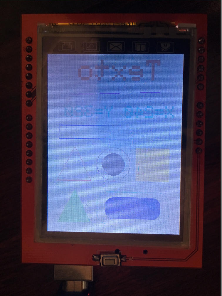
The code what you can see below is works but I had changed the ID to 0x9325 directly. (tft.begin(0x9325))
It is not mine TFT's ID but the result is more than nothing...
The result is on the attached picture. The screen is mirrored and flickered.

Big thanks in advance for any idea!

The CODE;

#include <SPFD5408_Adafruit_GFX.h>
#include <SPFD5408_Adafruit_TFTLCD.h>

#define LCD_CS A3 // Chip Select - Pin analogico 3
#define LCD_CD A2 // Command/Data - Pin Analogico 2
#define LCD_WR A1 // LCD Write - Pin Analogico 1
#define LCD_RD A0 // LCD Read - Pin Analogico 0
#define LCD_RESET A4 // LCD Reset - Pin Analogico 4

Adafruit_TFTLCD tft(LCD_CS, LCD_CD, LCD_WR, LCD_RD, LCD_RESET); // Instancia del LCD

#define BLACK 0x0000
#define RED 0xF800
#define GREEN 0x07E0
#define WHITE 0xFFFF
#define BLUE 0x001F
#define CYAN 0x07FF
#define YELLOW 0xFFE0
#define MAGENTA 0xF81F

void setup(void)
{
tft.begin(0x9325); // Iniciamos el LCD especificando el controlador de nuestro LC. En este caso el ILI9341.
// Otros controladores: 0x9325, 0x9328,0x7575, 0x9341, 0x8357.

tft.fillScreen(BLACK); // Colocamos el fondo del LCD en Negro
}

void loop(void)
{
tft.setRotation(0); // Establecemos la posición de la pantalla Vertical u Horizontal

tft.setCursor(40, 10); // Situamos el cursor en la posicion del LCD deseada,
// (X, Y) siendo X el ancho (240 px max.) e Y el alto (320 px max.)

tft.setTextSize(5); // Definimos tamaño del texto. (Probado tamaños del 1 al 10)

tft.setTextColor(CYAN); // Definimos el color del texto

tft.println("Texto"); // Escribimos nuestro texto en el LCD. Realizará un salto de linea
// automatico si el texto es mayor que el tamaño del LCD

tft.drawLine(20, 65, 200, 70, GREEN); // Dibujamos una linea (Punto inicio X, Punto inicio Y, Punto final X, Punto final Y, Color)

int X = tft.width(); // Almacenamos en la variable entera X el ancho del LCD en pixeles mediante tft.width();
int Y = tft.height(); // Almacenamos en la variable entera Y el alto del LCD en pixeles mediante tft.height();

tft.setCursor(15, 90); // Situamos el cursor en una nueva posicion del LCD

tft.setTextSize(3); // Definimos tamaño del texto.

tft.setTextColor(RED); // Definimos el color del texto

tft.print("X="); tft.print(X, DEC); // Imprimimos por pantalla el valor de las variables en decimal
tft.print(" Y="); tft.println(Y, DEC);

tft.drawRect(20, 125, 200, 25, YELLOW); // Dibujamos un cuadrado/rectangulo sin color de relleno
// (Punto inicial X, Punto inicial Y, Longitud X,Longitud Y, Color)

tft.fillRect(20, 165, 60, 60, BLUE); // Dibujamos un cuadrado/rectangulo relleno de color
//(Punto inicial X, Punto inicial Y, Longitud X,Longitud Y, Color)

tft.drawCircle(120, 195, 30, WHITE); // Dibujamos un circulo sin color de relleno
//(Punto inicial X, Punto inicial Y, Radio del circulo, Color)

tft.fillCircle(120, 195, 20, WHITE); // Dibujamos un circulo relleno de color
//(Punto inicial X, Punto inicial Y, Radio del circulo, Color)

tft.drawTriangle // Dibujamos un triangulo sin color de relleno
(190, 163, // (Vertice superior X, Vertice superior Y,
160, 225, // Vertice inferior izquierdo X, vertice inferior izquierdo Y,
222, 225, CYAN); // Vertice inferior derecho X, Vertice inferior derecho Y, Color)

tft.fillTriangle // Dibujamos un triangulo relleno de color
(190, 240, // (Vertice superior X, Vertice superior Y,
160, 302, // Vertice inferior izquierdo X, vertice inferior izquierdo Y,
222, 302, MAGENTA); // Vertice inferior derecho X, Vertice inferior derecho Y, Color)

tft.drawRoundRect(20, 245, 130, 60, 20, RED); // Dibujamos un cuadrado/rectangulo con los bordes redondeados sin color de relleno
// (Punto inicial X, Punto inicial Y, Longitud X,Longitud Y, Radio de los vertices, Color)

tft.fillRoundRect(35, 255, 100, 40, 15, YELLOW); // Dibujamos un cuadrado/rectangulo con los vertices redondeados relleno de color
// (Punto inicial X, Punto inicial Y, Longitud X,Longitud Y, Radio de los vertices, Color)
delay(10000);
}

Update;

I found a sketch what was able to read my TFT.
This is the Result;

Read Registers on MCUFRIEND UNO shield
controllers either read as single 16-bit
e.g. the ID is at readReg(0)
or as a sequence of 8-bit values
in special locations (first is dummy)

reg(0x0000) 15 05 ID: ILI9320, ILI9325, ILI9335, ...
reg(0x0004) 00 00 00 00 Manufacturer ID
reg(0x0009) 00 00 00 00 00 Status Register
reg(0x000A) 00 00 Get Powsr Mode
reg(0x000C) 00 00 Get Pixel Format
reg(0x0061) 00 00 RDID1 HX8347-G
reg(0x0062) 00 00 RDID2 HX8347-G
reg(0x0063) 00 00 RDID3 HX8347-G
reg(0x0064) 00 00 RDID1 HX8347-A
reg(0x0065) 00 00 RDID2 HX8347-A
reg(0x0066) 00 00 RDID3 HX8347-A
reg(0x0067) 00 00 RDID Himax HX8347-A
reg(0x0070) 00 00 Panel Himax HX8347-A
reg(0x00A1) 00 00 00 00 00 RD_DDB SSD1963
reg(0x00B0) 00 00 RGB Interface Signal Control
reg(0x00B4) 00 00 Inversion Control
reg(0x00B6) 00 00 00 00 00 Display Control
reg(0x00B7) 00 00 Entry Mode Set
reg(0x00BF) 00 00 00 00 00 00 ILI9481, HX8357-B
reg(0x00C0) 00 00 00 00 00 00 00 00 00 Panel Control
reg(0x00C8) 00 00 00 00 00 00 00 00 00 00 00 00 00 GAMMA
reg(0x00CC) 00 00 Panel Control
reg(0x00D0) 00 00 00 Power Control
reg(0x00D2) 00 00 00 00 00 NVM Read
reg(0x00D3) 00 00 00 00 ILI9341, ILI9488
reg(0x00DA) 00 00 RDID1
reg(0x00DB) 00 00 RDID2
reg(0x00DC) 00 00 RDID3
reg(0x00E0) 00 00 00 00 00 00 00 00 00 00 00 00 00 00 00 00 GAMMA-P
reg(0x00E1) 00 00 00 00 00 00 00 00 00 00 00 00 00 00 00 00 GAMMA-N
reg(0x00EF) 00 00 00 00 00 00 ILI9327
reg(0x00F2) 00 00 00 00 00 00 00 00 00 00 00 00 Adjust Control 2
reg(0x00F6) 00 00 00 00 Interface Control

So I found in this result;
ILI9320, ILI9325, ILI9335, ILI9341, ILI9488, ILI9327, ILI9481

It looks to much to find the proper library for this...

Perhaps you should drink less Brandy at this hour in the morning!

You have a Renesas R61505 controller.
It is fairly similar to an ILI9325.

The R61505V and R61505W are supported by MCUFRIEND_kbv library.
If you wait for 60 seconds, I will add R61505 to MCUFRIEND_kbv library on GitHub.

David

Edit. GitHub has been updated. Download the ZIP. Install ZIP library from the Sketch Menu in the IDE.

I do not own R61505, R61505V or R61505W. I rely on Users to report any problems. This controller should do everything except for Band Scroll (it can only scroll the whole screen).