Please run the LCD_ID_readreg sketch and copy-paste the Serial output to a message.

As I am at a PC, your JPEG was easy to view.
For future reference, copy-paste from the Serial is far more convenient to your readers.
You have a LGDP4532 controller.
My library supports the LGDP4535 but you need to #define SUPPORT_4535
I suggest that you do the #define and force tft.begin(0x4535)
Let me know the result. Wrong colours, mirroring etc is easy to fix.
If you still get the missing pixels, I would just buy a replacement shield.
David.
OK, Thanks David thank you for help.
I understand that that "Your library" that is Adafruit_GFX.h and MCUFRIEND_kbv.zip.
On serial out the effect is:
Serial took 0ms to start
ID = 0x4532
But screen white as snow ![]()
I think I have broken display.
Edit the mcufriend_kbv.cpp file. Add
#define SUPPORT_4535
And in every example, force the ID to 0x4535. e.g.
tft.begin(0x4535);
I am not very optimistic.
But it is worth trying.
A replacement 2.4" shield can be bought in the UK. Or very cheaply from China.
David.
I know. I did as you wrote, but no effect. Only TFTLCD.h library partially running.
I bought display in aliexpress and that I have a refund. Then i buy new.
Thank you for your time.
Thanks so much for all this great stuff. Unfortunately I've run into an issue that I cannot figure out. I was building a simple LCD that would pull bitmaps from the SD card. I split the touchscreen into quadrants so I could have next/prev/up/down buttons, and could change bitmaps that way. I've got all that code done, then I moved into getting the bitmaps to display.
I've been able to get bitmaps to display, and do whatever I want with the LCD. The problem I'm having is that as soon as I call
TSPoint p = ts.getPoint();//ts = TouchScreen object
within the loop to get touch coordinates, any time I try to do anything to the LCD after that, either nothing happens or the screen goes white and fails.
I've got two of these and both do the same thing. I've tried multiple Arduino boards. It's weird. Took me forever to figure out that the call for the touch point was causing my issue.
Details:
Arduino Mega 2560 R3 (multiple versions)
LCD Touchscreen: https://amzn.com/B00UAA2XIC
Any idea why a call to do anything to the LCD wouldn't work after doing ts.getPoint()?
Because the Touch pins are shared with the TFT control pins.
You have to call pinMode() for YP, XM after you use getPoint()
This is mentioned in every example.
David.
Excellent info. Thank you for pointing me in the right direction.
Definitely not mentioned in every example. touchscreendemo.ino has nothing about it, and tftbmp_UNOyMEGA.ino only says something about doubling up the pins. graphicstest.ino and rotationtest.ino also have no mention. The only example that uses pinMode() is tftpaint2.ino, which I have not had to look at until now, and only because you pointed it out. So, thanks again. I've got it working properly now.
Hello,
-about 2.4 TFT screen with 0x4532 controller
I have read the remarks by David Prentice on the shields with 0x4532 controllers, and I have used the mcufriend library and followed the instructions below. Finally some life into the shield. However....., only half the screen is working. You can see the result at:
")
What can I do to get the screen fully working?
Any help is appreciated! Thanks in advance!
Regards, Leodino
david_prentice:
Edit the mcufriend_kbv.cpp file. Add#define SUPPORT_4535And in every example, force the ID to 0x4535. e.g.
tft.begin(0x4535);I am not very optimistic.
But it is worth trying.A replacement 2.4" shield can be bought in the UK. Or very cheaply from China.
David.
Based on the mcufriend libray and some other info I have this little 2.4 TFT with 0x4532 (LGDP4532) working now.
Follow the approach mentioned by David in this thread and add #define SUPPORT_4532 in the mcufriend_kbv.cpp file.
Also in the mcufriend_kbv.cpp file add the following code:
#ifdef SUPPORT_4532
//Support for LG Electronics LGDP4532 (also 4531 i guess) by Leodino v1.0 2-Nov-2016
//based on data by waveshare and the datasheet of LG Electronics
//My approach to get it working: the parameters by waveshare did no make it function allright
//I started with remming lines to see if this helped. Basically the stuff in range 41-93
//gives problems.
//The other lines that are REMmed give no problems, but it seems default values are OK as well.
case 0x4532:
	_lcd_capable = 0 | REV_SCREEN;  // | INVERT_GS;
	static const uint16_t LGDP4532_regValues[] PROGMEM = {
		0x0000,0x0001, //Device code read
		0x0010,0x0628, //Power control 1 SAP[2:0] BT[3:0] AP[2:0] DK DSTB SLP
		0x0012,0x0006, //Power control 3 PON VRH[3:0]
		//0x0013,0x0A32, //Power control 4 VCOMG VDV[4:0] VCM[6:0]
		0x0011,0x0040, //Power control 2; DC1[2:0] DC0[2:0] VC[2:0]
		//0x0015,0x0050, //Regulator control RSET RI[2:0] RV[2:0] RCONT[2:0]
		0x0012,0x0016, //Power control 3 PON VRH[3:0]
		TFTLCD_DELAY,50,
		0x0010,0x5660, //Power control 1 SAP[2:0] BT[3:0] AP[2:0] DK DSTB SLP
		TFTLCD_DELAY,50,
		//0x0013,0x2A4E, //Power control 4 VCOMG VDV[4:0] VCM[6:0]
		//0x0001,0x0100, //Driver output control SM SS
		//0x0002,0x0300, //LCD Driving Wave Control
		//0x0003,0x1030, //Entry mode TRI DFM  BGR  ORG I/D[1:0] AM
		//0x0007,0x0202, //Display Control 1 PTDE[1:0] BASEE GON DTE COL D[1:0]
		TFTLCD_DELAY,50,
		//0x0008,0x0202, //Display Control 2 FP[3:0] BP[3:0] front and back porch (blank period at begin and end..)
		//0x000A,0x0000, //Test Register 1 (RA0h)
		//Gamma adjustment
		0x0030,0x0000,
		0x0031,0x0402,
		0x0032,0x0106,
		0x0033,0x0700,
		0x0034,0x0104,
		0x0035,0x0301,
		0x0036,0x0707,
		0x0037,0x0305,
		0x0038,0x0208,
		0x0039,0x0F0B,
		TFTLCD_DELAY,50,
		//some of this stuff in range 41-93 really throws things off....
		//0x0041,0x0002,
		//0x0060,0x2700, //Driver Output Control (R60h)
		//0x0061,0x0001, //Base Image Display Control (R61h)
		//0x0090,0x0119,   //Panel Interface Control 1 (R90h) DIVI[1:0]  RTNI[4:0]
		//0x0092,0x010A,  //Panel Interface Control 2 (R92h)  NOWI[2:0] EQI2[1:0] EQI1[1:0]
		//0x0093,0x0004, //Panel Interface Control 3 (R93h) MCPI[2:0]
		//0x00A0,0x0100, //Test Register 1 (RA0h)
		TFTLCD_DELAY,50,
		0x0007,0x0133, //Display Control 1 PTDE[1:0] BASEE GON DTE COL D[1:0]
		TFTLCD_DELAY,50,
		//0x00A0,0x0000, //Test Register 1 (RA0h)
		};
	init_table16(LGDP4532_regValues, sizeof(LGDP4532_regValues));
	break;
#endif
Greetings and thanks to all programmers.
Hi i bought the following tft for use with arduino Mega
This is what I get from LCD_ID_readreg
Read Registers on MCUFRIEND UNO shield
controllers either read as single 16-bit
e.g. the ID is at readReg(0)
or as a sequence of 8-bit values
in special locations (first is dummy)
reg(0x0000) 00 00 ID: ILI9320, ILI9325, ILI9335, ...
reg(0x0004) 00 00 00 00 Manufacturer ID
reg(0x0009) 00 00 00 00 00 Status Register
reg(0x000A) 08 08 Get Powsr Mode
reg(0x000C) 66 66 Get Pixel Format
reg(0x0061) 00 00 RDID1 HX8347-G
reg(0x0062) 00 00 RDID2 HX8347-G
reg(0x0063) 00 00 RDID3 HX8347-G
reg(0x0064) 00 00 RDID1 HX8347-A
reg(0x0065) 00 00 RDID2 HX8347-A
reg(0x0066) 00 00 RDID3 HX8347-A
reg(0x0067) 00 00 RDID Himax HX8347-A
reg(0x0070) 00 00 Panel Himax HX8347-A
reg(0x00A1) 00 00 00 00 00 RD_DDB SSD1963
reg(0x00B0) 00 00 RGB Interface Signal Control
reg(0x00B4) 00 00 Inversion Control
reg(0x00B6) 00 00 00 00 00 Display Control
reg(0x00B7) 00 00 Entry Mode Set
reg(0x00BF) 01 01 22 15 81 00 ILI9481, HX8357-B
reg(0x00C0) 00 00 3B 00 02 00 01 00 43 Panel Control
reg(0x00C8) 00 00 00 00 00 00 00 00 00 00 00 00 00 GAMMA
reg(0x00CC) 00 00 Panel Control
reg(0x00D0) 00 00 00 Power Control
reg(0x00D2) 03 03 24 04 00 NVM Read
reg(0x00D3) 03 03 24 04 ILI9341, ILI9488
reg(0x00DA) 00 00 RDID1
reg(0x00DB) 00 00 RDID2
reg(0x00DC) 00 00 RDID3
reg(0x00E0) 00 00 00 00 00 00 00 00 00 00 00 00 00 00 00 00 GAMMA-P
reg(0x00E1) 00 00 00 00 00 00 00 00 00 00 00 00 00 00 00 00 GAMMA-N
reg(0x00EF) 00 00 00 00 00 00 ILI9327
reg(0x00F2) 07 07 00 00 00 00 00 00 00 00 00 00 Adjust Control 2
reg(0x00F6) 00 00 00 00 Interface Control
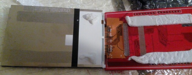
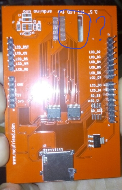
But it think the monitor is problematic, it seems it is missing a bus-wire? (check the attachment)
is it true? or simply another model that doesn't need it?
You have a Renesas R61581 and it should work with the Beta library on GitHub. ID = 0x1581.
I would guess that the bare display module flex ribbon is soldered to the underside of your pcb.
It is not uncommon to design a pcb for several hardware options.
The pcb seems to have a footprint for a SPI Flash memory.
And some other mystery components at the top left.
Does it work ?
David.
Thank you for your reply,
no it doesn't work, i see only white backlight (connected to Mega, a) directly as a shield and b) with cables to pins 22-29 and 38-40
in sellers' auction the ribbon is there ![]() (I have communicated the problem to him and wait for confirmation)
(I have communicated the problem to him and wait for confirmation)
by the way how did you figured out the Renesas R61581 and the ID = 0x1581???
david_prentice:
You have a Renesas R61581 and it should work with the Beta library on GitHub. ID = 0x1581.
I would guess that the bare display module flex ribbon is soldered to the underside of your pcb.
It is not uncommon to design a pcb for several hardware options.
The pcb seems to have a footprint for a SPI Flash memory.
And some other mystery components at the top left.Does it work ?
David.
reg(0x00BF) 01 01 22 15 81 00 ILI9481, HX8357-B
This shows that it is Renesas R61581.
The library is designed for proper Shields.
If you want to use a bare module, it is your responsibility to wire it correctly.
no it doesn't work, i see only white backlight (connected to Mega, a) directly as a shield and b) with cables to pins 22-29 and 38-40
This implies that you have connected 5V GPIO to a 3.3V module. This is almost guaranteed to fry your controller.
David.
Thank you once more,
I saw this Touch Screen on the Arduino Mega 2560 – misc.ws
and supposed it should be OK!, when plugging the screen to Mega, 3.3V and 5V and Ground goes to the correct positions, this implies also for the analog pins.
I thought that this lcd could be used as a shield
is it possible to send me a link to the "proper shield"?
david_prentice:
The library is designed for proper Shields.
If you want to use a bare module, it is your responsibility to wire it correctly.
This implies that you have connected 5V GPIO to a 3.3V module. This is almost guaranteed to fry your controller.
David.
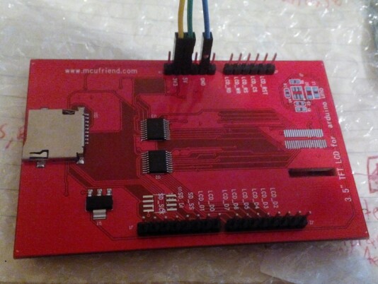
The misc.ws site has this regular Uno shield:
Your Ebay item looks like
In other words, they are both "Uno-style" shields.
Uno Shields are designed to mate intimately with the Uno, Mega, Due, Zero, ... boards
Mega Shields have lots more pins. They can only mate intimately with the Mega, Due
I am horrified by people connecting flying leads from a 5V MEGA2560 to a Shield. Shields are designed to plug into the Arduino.
Your display shield should work fine with Beta library on GitHub.
If your display can still report the correct values from LCD_ID_readreg sketch, it should work with all the examples in the Beta library.
David.
David my shield is exactly the one in your picture (except that the wire-ribbon is missing check attachment), in the auction it is exactly the same. I Believe the ribbon should be there because..... I separated the screen from the shield-board and it seems there are connections leading to nowhere... should be to ribbon and the to the back side like the photo, and that's why it is not working.
I just copied the lower photo from the Ebay link and inserted the image into the message.
As I replied in a previous message, pcbs are often designed for different options. I have shields with unused pads.
If you plug the shield into the Mega and the LCD_ID_readreg sketch reports correct values, there must be a R61581 controller present. The top photo in #256 shows you how to plug a shield into an Arduino.
I am even more horrified that you have dismantled the shield as well as connecting flying wires. Perhaps you have fried it or broken ribbons, connectors, ...
David.
Dear David,
I think you got some things wrong.
I did not dismantled the screen, there is a soft white pad that holds the screen on the shield, I cut it (there are no wires involved) and you can see in the photo that indeed there is a place that a ribbon should be and there are paths going nowhere.
In addition when I connected it in pins 22-29 of Mega I used breadbord wires (check the second photo), there were never connected flying wires or anything similar.
(you can check the attached photos)
in this discussion Help with TFT LCD 3.6" OR 3.5" - Displays - Arduino Forum MosheB have bought the same screen, I am waiting for his confirmation that his ribbon exist or not
david_prentice:
I just copied the lower photo from the Ebay link and inserted the image into the message.As I replied in a previous message, pcbs are often designed for different options. I have shields with unused pads.
If you plug the shield into the Mega and the LCD_ID_readreg sketch reports correct values, there must be a R61581 controller present. The top photo in #256 shows you how to plug a shield into an Arduino.
I am even more horrified that you have dismantled the shield as well as connecting flying wires. Perhaps you have fried it or broken ribbons, connectors, ...
David.