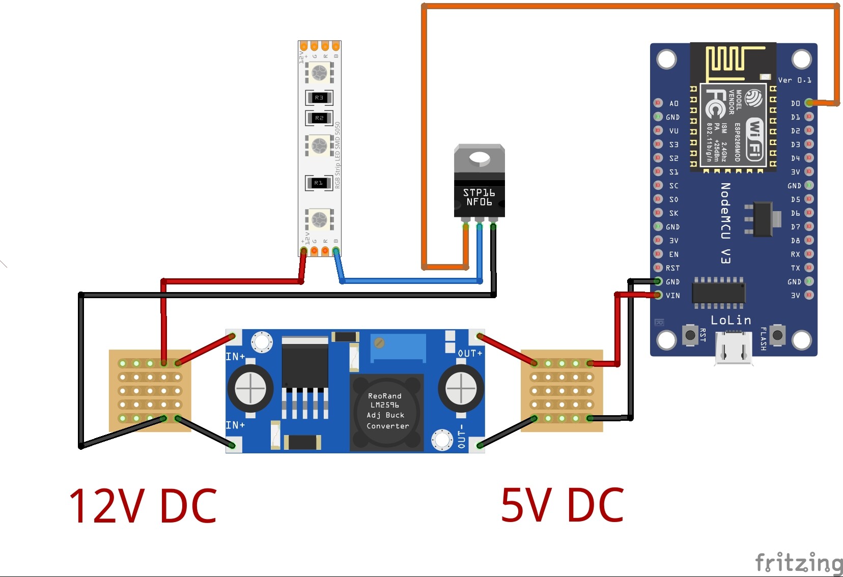
I've got an LED strip (non-RGB) which I'm trying to control via a NodeMCU. I'm currently using Blynk for the project. When the LED strip is connected directly to 12V, it's super bright, however; when controlling via PWM @ the max value of 1024, it's much dimmer. Below is the hardware layout I'm using. The code is simple as it simply adjusts the PWM of D0 between 0 & 1023 on a slider.
Any suggestions to achieve max brightness when slider is at the top (PWN = 1024)?
septillion is spot on. The IRF520 is a Power Mosfet with 9.2A drain current and 100V breakdown voltage. The mosfet has a low gate threshold voltage of 4V and hence commonly used with microcontrollers like Arduino for switching high current loads. Note the 4V is not a logic level voltage compatible with the 3.5 output of your controller. The MOSFET will partally enhance but not fully hence there is a voltage drop across the MOSFET causing your dim LEDs. Heat the MOSFET and the brightness will change. This is temperature dependent so keep it below 100C.
@Grumpy_Mike On a ESP8266 PWM is 10-bit So I assumed (but something with mother of all...) his mention of 1024 was just a typo after mentioning 0-1023.
On an ESP32 the PWM can be generated by several sources. Mainly PWM for LED's are driven by the ESP32 LED API.
#include "esp32-hal-ledc.h"

void setup()
{
  ledcSetup( 6, 12000, 8 ); // ledc: 4  => Group: 0, Channel: 2, Timer: 1, led frequency, resoulition bits // blue led
  ledcAttachPin( GPIO_NUM_14, 6 );   // gpio number and channel
  ledcWrite( 6, 0 ); // write to channel number 6
}
//
void fDoRed( void * paramater )
{
  bool UpDown = true;
  int countUpDown = 0;
  for( ;; )
  {
     xEventGroupWaitBits (eg, evtDoRed, pdTRUE, pdTRUE, portMAX_DELAY );
     // send led data, increment led count, determine end stops and direction
    if ( UpDown )
    {
      countUpDown++;
    } else {
      countUpDown--;
    }
    if ( countUpDown <= 0 )
    {
      UpDown = true;
    }
    if ( countUpDown >= 255 )
    {
      UpDown = false;
    }
    //log_i( "red %d", countUpDown );
    ledcWrite( 6, countUpDown ); // write to channel number 4
    //
  }
   vTaskDelete( NULL );
}
This line of code ledcSetup( 6, 12000, 8 ); // ledc: 4 => Group: 0, Channel: 2, Timer: 1, led frequency, resolution bits // blue led, which, if using the ESP32 Arduino core is hidden, sets the number of bits at 8. If you want to use 1024 then use the API and set the bits to use as 10 instead of 8.
A look into the ESP8266 API might give hints on how to set 10 bits for the ESP8266 PWM.
Yes, 1024 was a typo as I meant 1023 - must had been thinking resolution
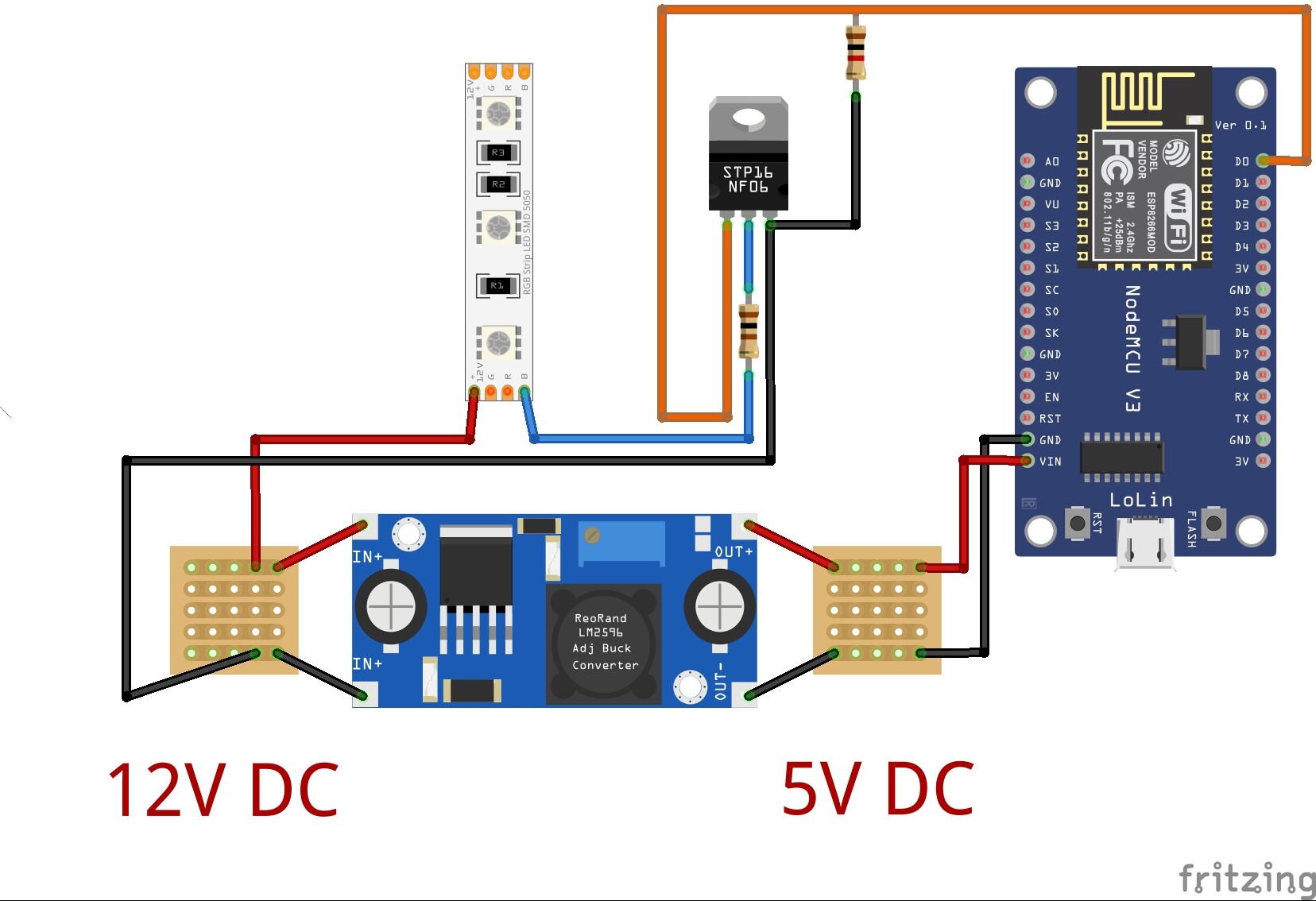
Assuming the only resolution is still the MOSFET, what should I replace the IRF520 with? I've got a few N-Channel RFP30N06LE's which are listed as having a logic level gate which I assume would work. If so, would a resistor or anything else need to be placed inline with it or would the below schematic work?
Note: Please ignore the label of the MOSFET in the image. I'd be using a RFP30N06L unless something else is required.
That RFP30N06LE seems very suitable, wayyyy more than the IRF520 . Strictly speaking drive a gate directly can overload to output of a micro. So best practice is to use a 50-100Ω resistor in line to the gate. But usually I'm naughty and don't bother. And if you want to be sure the LED's stay of when the ESP is booting/resetting, place a 1k-100k pull down between gate and source.
Awesome - Thanks - Will try it out this afternoon...
Not too familiar with pull down resistors - are they just standard resistors used in a specific way or engineered differently? If I use one, I guess the below would be the final then, right?
Note: Resistor on gate being 100 & one between gate & source being 1k...
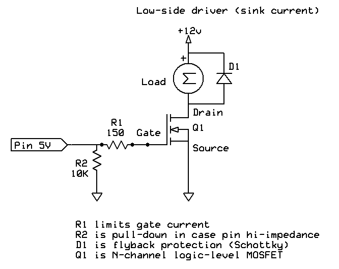
The 150 Ohm resistor goes between the ESP output and the FET gate, it limits the current the ESP requires to charge and discharge the gate capacitance which is quite significant.
At power-up, until the ESP initialises, its GPIOs float so the random voltage on the FET gate may allow it to at least partially turn on. This may or may not matter in respect of the LED strip briefly flashing and the partially turned on FET dissipating some power whilst it does so. Likely no worse than the original situation you describe, however to avoid this you can put a 10k resistor between the ESP GPIO and ground, before the series 150 Ohm resistor. Like this:
Turns out the reference article I was using had the pinout for the MOSFET incorrectly labeled with the gate being the middle pin which was the confusion. Good to go now, I think.
@bzowk Tip, always go by the datasheet. And now you know why most of us don't like Fritzing Although it's possible to make a real schematic with Fritzing.
Turns out the reference article I was using had the pinout for the MOSFET incorrectly labeled with the gate being the middle pin which was the confusion.
Different FETs have different pin outs, as do transistors and many other components. Always check first. Your article was probably right but for the FET they used. Even some transistors have a suffix which denotes a different pin out.