I'm looking to drive a 5v logic pin based on detecting a current in a 12v (auto) system. The 12v signal will be noisy and could fluctuate some (switches and loads and such). I have software debouncing for switches but the fluctuations might sustain longer than a debounce is good for. I want the simplest possible (but reliable) solution, i.e., fewest components (one would be great) and not an overkill circuit that kills an ant with dynamite.
My thought was a non-inverting Schmitt trigger would be a good choice to clean up the noise and produce a nice, clean, square logic signal. There are cheap dedicated Schmitt ICs or simple op amp/transistor circuits that would do the job; but the output is still 12v. A voltage divider (before or after the trigger) with just a couple resistors is an option to reduce the voltage but it feels a little hackneyed and won't really hand major voltage fluctuations, especially overvoltage situations, as automotive voltage dances around a lot.
How would you solve this?
[Edit] I should have included in my post that I'm using a GPIO interrupt. So polling is not on the table.
Thanks, LarryD. I should have included in my post that I'm using a GPIO interrupt. So polling is not on the table. But the idea of debouncing into a voltage divider makes sense.
The thing I like about schmitt triggers is the simplicity of the circuit, the reliability of the hysteresis range and the cleanliness of the signal.
Opto couplers are also very simple, but I still worry about the noise. But I suppose your solution to debounce the signal would be effective.
I am putting a tap on the wires I want to monitor. When a device is turned on, the wire goes hot, and I will read the voltage as a signal. So, technically, I'm not detecting a specific current... just the presence of voltage, i.e., any current at all. The devices are motors and lights that draw multiple amps of current, so I don't imagine any circuit I introduce will impact operation.
RE interrupts, the device may be dormant for months at a time and so needs to go to sleep when inactive to conserve battery power and wake when a voltage signal is detected at the interrupt pin.
It seems if there is enough power/amps for the lights and motors to operate, there would be sufficient power for the Arduino.
What turns on the lights and motors ? is everything 12VDC ?
What are we missing ?
Please tell us what you are monitoring and why you need to do this ?
You can wake the Arduino every now and then, check for input changes, record things, then go back to sleep.
This would take very little power.
Let’s see your proposed schematic of what you perceive the project will entail .
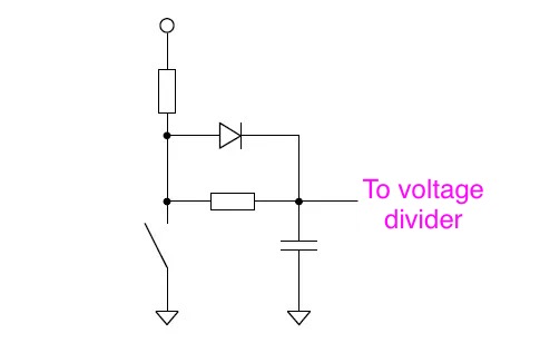
LM339
Set the input threshold to 6V (2 resistors). Use a pullup (1 resistor) to 5V on the output.
Safe for the Arduino and simple. No debounce needed can be used with interrupts
But the presence of "voltage" does not in any way mean there is "current" flowing. If you want to measure current, then measure current. The presence of voltage just means there is connection made to the voltage source.
@LarryD In answer to your question about what I'm up to...
First, this is for fun. I'm a maker. An amateur to be sure. But I'm also a career software engineer who's been tinkering in electronics for 40 years. I have in mind a number of Arduino/ESP32-based automation projects -- sensors driving actions in physical devices. I don't have a schematic because I'm in feasibility mode. I'm gathering the understanding of what's possible so that I can piece together the necessaries for different projects.
For example, a rabbit hutch that automatically closes its gate whenever the bunny steps on the floor sensor after a certain time of day and then opens the gate a set time the next morning... and the heater will turn on when the temperature dips. The gate might be controlled by a 12V servo motor or linear actuator. The gate can also be opened/closed via wireless remote. And, of course, the heater turns on if the temperature dips and a text gets sent when the water bottle is approaching empty. Fun, right?
I have a bunch of these. As an easy first project, I'm gonna turn the headlights off in my 1977 F150 after the key is turned off. I am tapping the accessor line of the ignition switch so that I know when the key is on/off. I'm tapping the running light line so that I know when the light switch is on/off; this is possible because the running lights are on a different power circuit than the headlights.) A latching relay will be inserted into the headlight power supply, flipped on and off based on the algorithm instantiated in the ESP32's code. The delay is variable, set by a rotary encoder. The state of the ignition, the headlight switch and the delay setting are all displayed on a 1.9" SSD-1306 OLED display. Fun, right?