Convert LED into a digital signal

Hello everyone, I have a PCB that uses a small LED to display its status. I would like to remove the LED and wire the contact pads to an ESP32 to get the signal.

I've measured the voltage across the LED and it's about 2.7V. Without the LED the voltage is about 3.8V, it's always blinking so I don't know if the readings are accurate.

Can I just wire the LED contact pads to the ESP32, with a voltage divider in between to bring down the voltage to below 3.3V, or I will damage the ESP32? The two boards will be powered by the same power source.

Thanks for the help

Use an opto-coupler when joining two circuits together to minimise the risk.

Generally yes, but you should verify the circuit voltage. Try to measure it somewhere on the circuit where voltage is static.
What about using phototransistor to read the LED without modifying the circuit?

The best way is to replace the LED with an opto coupler (post#3)
Connect the transistor side to ESP pin and ESP ground, with it's internal pullup enabled.
No other parts required.
Leo..

I thought about it, I'm worried about the "quality" of the signal. The LED is always blinking, it blinks at a different speed to indicate the status. If the LED was just on and off I would use a phototransistor but since the LED is always blinking I'm worried that I will not able to differentiate the status

Is the pc817 ok? Or are there better alternatives?

If you do it correctly, LED + phototransistor equals to optocoupler.
Anyway, if soldering is not a problem, I suggest optocoupler for simplicity.

Yes.
You can leave the original LED in place, since the LED in the opto works on a lower voltage.
An opto LED is about 1.25volt vs. 1.8volt for a common red indicator LED.
Just connect the opto Led across the original one. Or in series if you still want to see it.
Polarity matters.
Leo..

So write some code that resets every time it blinks, but raises a flag when a certain period of time with no blink has elapsed.

If this is not something you can just do, it should be.

For now, what you can search for is a "missing pulse detector" or a "keep alive" mechanism.

You could use hardware but it is better to just use code. When I am in the lab I will find the demonstration of that, several in fact, that I've seen on these fora.

    if the LED is on
        reset a timer
        turn on your version of the signal


    if the timer runs up to, say, 777 milliseconds
        turn off your own version of the signal

Literally two if statements.

Timers can be based on the millis() function.

L8R

a7

Odds are that the LED is driven by a logic signal at one end or the other. It's most common for the anode (+) to be connected to 3V by a resistor and the cathode (-) driven to GND by logic. If you can confirm this, then you can simply connect the ESP32 to the logic signal.

However, optical coupling is safest.

You will have that problem no matter how the LED blinking is read by the ESP32. What details do you have about what the different rates of LED blinks indicate ?

It sounds like you need to determine the period of the LED blinking, ie the time between the LED turning on and turning on again. It will not matter how many times you do that because if the period has not changed then the LED will still be indicating the same state

I don't have a precise timing since the project is still in the "can it be done?" stage.

Judging by eye a delay of 500ms means it's connected, a delay of 250ms means it's not connected/looking for a Bluetooth connection

With the rate being so slow and the difference between the blink rates being so large it should be easy to detect the difference

Hi @Katoz ,

here is an example how to measure the blink rate with a non-blocking function (it is actually the same class as used for a button):

/*
  Forum: https://forum.arduino.cc/t/convert-led-into-a-digital-signal/1380846
  Wokwi: https://wokwi.com/projects/430758590508506113

  Example how to measure a blink rate non-blocking

  ec2021
  2025/05/12

*/


constexpr byte blinkOut {17};
constexpr byte switchPin {12};
unsigned long blinkRate;

constexpr byte blinkIn {5};
constexpr unsigned long connectRate {500};
constexpr unsigned long disConnectRate {250};
constexpr long          tolerance {25};


class InputDevice {
  private:
    unsigned long lastChange = 0;
    unsigned long lastDelta = 0;
    byte lastState = HIGH;
    byte state = LOW;
    byte pin;
  public:
    void init(byte aPin) {
      pin = aPin;
      pinMode(pin, INPUT_PULLUP);
      state = !digitalRead(pin);
    }
    boolean changedState() {
      byte actState = digitalRead(pin);
      if (actState != lastState) {
        lastDelta = millis() - lastChange;
        lastChange = millis();
        lastState = actState;
      }
      if (lastState != state && millis() - lastChange > 100) {
        state = lastState;
        return true;
      }
      return false;
    }
    boolean getState() {
      return state;
    }
    unsigned long getlastDelta() {
      return lastDelta;
    }
};

InputDevice button;
InputDevice signalIn;

void setup() {
  Serial.begin(115200);
  Serial.println("Start");
  blinkRate = disConnectRate;
  pinMode(blinkOut, OUTPUT);
  button.init(switchPin);
  signalIn.init(blinkIn);
}

void loop() {
  controlBlinkRate();
  blink();
  measureBlinkRate();
}

void measureBlinkRate() {
  static boolean errorPrinted = false;
  static unsigned long lastChange = 0;
  unsigned long delta = signalIn.getlastDelta();
  if (signalIn.changedState()) {
    errorPrinted = false;
    Serial.print("Last Delta: ");
    Serial.print(delta);
    if (insideTolerance(delta, connectRate)) {
      Serial.println("\tConnected");
      lastChange = millis();
    } else if (insideTolerance(delta, disConnectRate)) {
      Serial.println("\tDisconnected");
      lastChange = millis();
    } else {
      Serial.println("\tOut of tolerance!");
    }
  }
  if (millis() - lastChange > 4 * connectRate && !errorPrinted) {
    Serial.println("No changes detected!");
    errorPrinted = true;
  }
}

boolean insideTolerance(unsigned long value, unsigned long rate) {
  return (value <= rate + tolerance) && (value >= rate - tolerance);
}

void controlBlinkRate() {
  if (button.changedState()) {
    if (button.getState()) {
      blinkRate = disConnectRate;
    } else {
      blinkRate = connectRate;
    }
  }
}

void blink() {
  static unsigned long lastBlink = 0;
  static byte state = LOW;
  static long diff = 0;
  if (millis() - lastBlink >= blinkRate + diff) {
    diff = random(-tolerance / 2, tolerance / 2);
    lastBlink = millis();
    state = !state;
    digitalWrite(blinkOut, state);
  }
}

Feel free to check it out on Wokwi:

https://wokwi.com/projects/430758590508506113

The functions controlBlinkRate() and blink() are only required to simulate the incoming signal from an optocoupler or a different digital input.

The blink() function creates a random "blink jitter" and the evaluation of the measured signal delta uses a tolerance constant.

You can "cut" the signal wire using the switch on the right hand side. The sketch prints an error if the time between changes exceeds four times the connect rate.

Hope it is of assistance ...
Good luck!
ec2021

2 Likes

THX @ec2021 for the sketch and the wokwi demo.

I have used the same idea a few times. When there is a non-blocking resource-light sketch, one can stand up a testing functionality that produces inputs to test the main problem the sketch is hoping to solve. And maybe even reads outputs for verification.

IRL I have used a second Arduino board to do the same. So far, the wokwi makes using two Arduino boards difficult, and I haven't checked back since someone said it's not too bad. When I looked it didn't seem well-supported. So in the simulator, I just run the second sketch along side as was done here.

IDK if it is a terribly important technique, but it is a great deal of fun.

I had my own ideas about the main problem; I won't share my solution. I will say it was a bit more of a challenge than I first thought, partly because I tend to write before enough thinking has been done. Then I get late, and it's tired and hacking deserves all the criticism it garners. :expressionless:

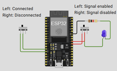
I like that the pulse simulation includes some random variations. I rearranged things so that the simulated pulse code was separate - the only connection between the solution code and the pulse generator were calls to a setup() and loop(), and one wire grabbing the pulse off the LED. Maybe it is so in the original - my first step was to understand just enough to rip the beating heart isolate and understand the pulse generation, so I wasn't paying too much attention.

Thorough testing was not easy even with the sidecar which was the pulse simulator. A stubborn flaw led me to wonder whether IRL one might want to count off a few pulses all of a same long (or short) nature before making any conclusion.

And just switching the pulse electrically made me look closer - I had to add some logic (I thought) to ignore narrow fractional pulses. When I found my real issues, I removed that and could not seem to switch the input on in such a manner as to present a spurious input to my algorithm.

Things like that bother me. So in a real deployment, I'd hate to see it go from missing pulses (unknown) to short detected and then stable reporting of long detection, and it would be unfortunate to make the higher level use of the detector account for that itself. Hence the counting off idea. At the expense of delaying the report.

All for a simple enough problem; one can see how any kind of real program could make testing and verification very difficult.

Here's the sketch with my logic removed, an blank page where one can write a solution in any way she desires.

// I used @ec2021's hardware and moved any code I repurposed "below the fold"
// 

// here an empty-ish sketch that just echoes the pulse generator

/*
  Forum: https://forum.arduino.cc/t/convert-led-into-a-digital-signal/1380846
  Wokwi: https://wokwi.com/projects/430758590508506113

  Example how to measure a blink rate non-blocking

  ec2021
  2025/05/12
*/

const byte optoInput = 27;      // the input from the monitored LED
const byte optoTellTale = 26;   // diagnostic: just follows the opto input

void setup() {
  // setup for @ec2021
  setupSimulatedPulse();

// rest of setup is for the detector

  pinMode(optoInput, INPUT_PULLUP);
  pinMode(optoTellTale, OUTPUT);
}

unsigned long lastPulseTime;    // the "alive" timer, time of last rising edge

void loop() {
//  service @ec2021 
  loopSimulatedPulse();

// rest of loop is for the detector
  
  digitalWrite(optoTellTale, digitalRead(optoInput));
}


//
// turtles from here on down. Just makes the pulse on pin 17
//

constexpr byte blinkOut {17};
constexpr byte switchPin {12};


// constexpr byte blinkIn {5};

constexpr unsigned long connectRate {500};
constexpr unsigned long disconnectRate {250};
constexpr long          tolerance {25};

void blink() {
  static unsigned long lastBlink = 0;
  static byte state = LOW;
  static long diff = 0;

  unsigned long blinkRate = digitalRead(switchPin) == LOW ? connectRate : disconnectRate;

  if (millis() - lastBlink >= blinkRate + diff) {
    diff = random(-tolerance / 2, tolerance / 2);
    lastBlink = millis();
    state = !state;
    digitalWrite(blinkOut, state);
  }
}

void setupSimulatedPulse()
{
  pinMode(blinkOut, OUTPUT);
  pinMode(switchPin, INPUT_PULLUP);
}

void loopSimulatedPulse()
{
  blink();
}


a7

1 Like

Hi @alto777 ,

thanks for sharing your thoughts and conclusions!

I also considered to wait for stable data but finally decided not to include it for different reasons but mainly that the optimum solution may quite likely depend on the specific application.

It might be a good idea to compare consecutive measurement data and create "quality criteria" that assist to decide when they are considered valid or not. E.g. one could use a counter variable that counts up until a given limit (e.g. 4) if the consecutive data are equal (with some tolerance) and down until zero if not. The parameters will depend on the real world application.

And - as you mentioned - these methods will of course create a certain delay. There's a trade-off between a safe and a quick decision.

Regards
ec2021

Another cool feature of the wokwi is that it has one of those inexpensive 24 MHz 8 channel logic anayzers available.

The mechanical switching off of the pulse input meant (in my sketch) that the input would immediately go HIGH.

A more comprehensive test would be allowing for the input to go LOW or HIGH; in any case asynchronous switching will def present pulses that are not valid.

On both sides of the unknown state the less than full pulse that switching creates can mean a cycle of a report in error.

So I am in agreement with myself and @ec2021 - no matter the exact method, counting off a number of equal value pre-conclusions or ignoring at least one pulse seems unavoidable.

And that is where I will leave it. I think.

It's s snippet, but here is my Output section. After learning that not all ESP32 GPIOs are GP, I managed to rig up some traffic lights, which makes these flaws easy to see. Red for disconnected, yellow for unknown and green for connected:

// print derived output of observed LED
// elsewhere :
// const byte trafficLEDs[3] = {25, 32, 33};
// char *outputTags[] = {"unknown", "connected", "disconnected"};
// enum outputNames {UNKNOWN, SLOW, FAST};

  static int printedOutput = -1;
  static int counter;
  if (printedOutput != output) {
    Serial.print(counter);
    Serial.print("  signal <");

    Serial.print(millis());
    Serial.print("> ");

    Serial.println(outputTags[output]);

    if (printedOutput >= 0) digitalWrite(trafficLEDs[printedOutput], LOW);
    digitalWrite(trafficLEDs[output], HIGH);

    counter++;
    printedOutput = output;
  }

a7

That is an odd voltage, are you sure you measured it correctly?

Nope. Or rather, I’ve measured correctly but I think the multimeter can’t pick up the voltage in that short time. That’s why I’m trying to find a an electronic shop that has an oscilloscope to measure it better

Well if you don't want to burnout your ESP32 it would be best to make sure.
Do you see a resistor anywhere that is connected to the LED?

Yes, it has a 2.2k resistor near the led. The voltage in is about 5.5V from a usb port (last time I’ve measured it was 5.8V, a little bit too high for a usb port)