K I will take a look 2nite thanks.
You have a penchant for understatement. ![]()
a7
Like I said, start small, I like this Wowki thing, still not clear on how to accomplish some things, but hey! Nice.
Just one LED on one cross point. Because
You might confuse row and column.
You might wire that one LED backwards.
By doing the least possible, you can get some confidence about that kind of thing.
This change to @flashko 's thing is where I would start.
@flashko how did you make the 8x8 matrix? Can ppl who want make they own parts? Or did you edit the 8x32? If you know, I be googling &c. to get a better grip on this useful tool and can only get better. TIA.
a7
I am starting to get busy again so I might not get to this for awhile. I get what your saying, thanks.
This is an awesome tool, thanks for the help
I edit on tab diagram.json line with "attrs": { "chain": "1" } - default is 4.
If anybody is trying to correlate the pins of the MAX7219 with the rows and columns of the matrix consider the diagram from the datasheet. I will probably employ this information in this project.

So… howzit coming along there @feltsg?
a7
//An integer to read a vertain channel
int readMux(int);

//Mux control pins
const byte s0 = 8;
const byte s1 = 9;
const byte s2 = 10;
const byte s3 = 11;

//Mux in "SIG" pin
int SIG_pin = 14;

//Max7219
const byte CS_PIN  = 3
const byte CLK_PIN = 4
const byte DIN_PIN = 5


//Holds a data type either true or false. bool var = val. Our variable is threshold.
boolean threshold = false;


//This is the number of devices adress starts counting at 0 even though there is only 1 device
#define MAX_SEG 1

//LED control Library
#include <LedControl.h>


LedControl matrix = LedControl (DIN_PIN, CLK_PIN, CS_PIN, MAX_SEG); // MAX7219

void setup ()
{
  //These lines are all setup for the Matrix


  //Switches from power saving to normal operation
  matrix.shutdown(0, false);

  //Controls the intensity  of the brightness takes value from 0-15 with setIntensity(int addr, int intensity)
  //Params:
  //  addr the address of the display to control
 //  intensity the brightness of the display.
//  void setIntensity(int addr, int intensity);
  matrix.setIntensity(0, 7);

  //This shuts all the LEDs of
  //Params is adress
  matrix.clearDisplay(0);


  //These lines are all setup for the 16 Channel Multiplexer

 // This makes the digital pin an output
  pinMode(s0, OUTPUT);
  pinMode(s1, OUTPUT);
  pinMode(s2, OUTPUT);
  pinMode(s3, OUTPUT);

  //It has an output of either GND or 5V. This sets the default as a pulldown.
  digitalWrite(s0, LOW);
  digitalWrite(s1, LOW);
  digitalWrite(s2, LOW);
  digitalWrite(s3, LOW);

//Here is a test LED for good measure. Also the built in LED is pin 13.
//Pinmode for LED 13
  pinMode(13, OUTPUT);
  digitalWrite(13, LOW);


  //This sets serial data transmission rate. Sets the data rate in bits per second.
  Serial.begin(9600);
}


//I dont know the mechanics of this, I guess its where we read the anaolog value at each (i).
//I am not worried about these lines just know they work. 86-122 if anyone can explain in a good way.
int readMux(int channel) {
  //array
  int controlPin[] = {s0, s1, s2, s3};

  int muxChannel[16][4] = {
    {0, 0, 0, 0}, //channel 0
    {1, 0, 0, 0}, //channel 1
    {0, 1, 0, 0}, //channel 2
    {1, 1, 0, 0}, //channel 3
    {0, 0, 1, 0}, //channel 4
    {1, 0, 1, 0}, //channel 5
    {0, 1, 1, 0}, //channel 6
    {1, 1, 1, 0}, //channel 7
    {0, 0, 0, 1}, //channel 8
    {1, 0, 0, 1}, //channel 9
    {0, 1, 0, 1}, //channel 10
    {1, 1, 0, 1}, //channel 11
    {0, 0, 1, 1}, //channel 12
    {1, 0, 1, 1}, //channel 13
    {0, 1, 1, 1}, //channel 14
    {1, 1, 1, 1} //channel 15
  };

  //cycle through the 4 sig
  for (int i = 0; i < 4; i ++) {
    digitalWrite(controlPin[i], muxChannel[channel][i]);
  }//close for loop

  //read the value at the SIG pin. //Read the value from the 16-channel multiplexor pin. This can only read one channel at a time.
  //and assign it to a variable.
  int analogValue = analogRead(SIG_pin);


  //Terminate a function and return a value from a function to the calling function, if desired.
  return analogValue;
}//close Adams super handy code part.


void loop() {
    //Loop through and read all 16 values
  //Reports back Value at channel i is: x
for (int i = 0; i < 16; i ++) {

    Serial.print("Value at channel ");
    Serial.print(i);
    Serial.print("is : ");
    Serial.println(readMux(i));
    Serial.print(" peeled state =  ");
    Serial.println(threshold);
	}


//Boolean holds a data type either true or false.
//use this way : bool varible = true or false. My variable is threshold.
//boolean threshold = false; (already made this a global)

//My for loop at channel 0
int analogValue = readMux(0)//how do I get this inside the if control strucure


   if (analogValue > 500) {
      threshold = true;

      void setLed(int 0, int row, int col, true)

    }//close if
    else {
      threshold = false;
      void setLed(int 0, int row, int col, false)

    }//close else


  }//close loop


//Adams thing to retrieve value.
//switch mux to channel 15 and read the value.
// int analogValue = readMux(15);
I used this sketch from this site to manage the 16-channel multiplexor CD74HC4067. I think its good.
http://adam-meyer.com/arduino/CD74HC4067
//Mux control pins
int s0 = 8;
int s1 = 9;
int s2 = 10;
int s3 = 11;

//Mux in "SIG" pin
int SIG_pin = 0;


void setup(){
  pinMode(s0, OUTPUT);
  pinMode(s1, OUTPUT);
  pinMode(s2, OUTPUT);
  pinMode(s3, OUTPUT);

  digitalWrite(s0, LOW);
  digitalWrite(s1, LOW);
  digitalWrite(s2, LOW);
  digitalWrite(s3, LOW);

  Serial.begin(9600);
}


void loop(){

  //Loop through and read all 16 values
  //Reports back Value at channel 6 is: 346
  for(int i = 0; i < 16; i ++){
    Serial.print("Value at channel ");
    Serial.print(i);
    Serial.print("is : ");
    Serial.println(readMux(i));
    delay(1000);
  }

}


int readMux(int channel){
  int controlPin[] = {s0, s1, s2, s3};

  int muxChannel[16][4]={
    {0,0,0,0}, //channel 0
    {1,0,0,0}, //channel 1
    {0,1,0,0}, //channel 2
    {1,1,0,0}, //channel 3
    {0,0,1,0}, //channel 4
    {1,0,1,0}, //channel 5
    {0,1,1,0}, //channel 6
    {1,1,1,0}, //channel 7
    {0,0,0,1}, //channel 8
    {1,0,0,1}, //channel 9
    {0,1,0,1}, //channel 10
    {1,1,0,1}, //channel 11
    {0,0,1,1}, //channel 12
    {1,0,1,1}, //channel 13
    {0,1,1,1}, //channel 14
    {1,1,1,1}  //channel 15
  };

  //loop through the 4 sig
  for(int i = 0; i < 4; i ++){
    digitalWrite(controlPin[i], muxChannel[channel][i]);
  }

  //read the value at the SIG pin
  int val = analogRead(SIG_pin);

  //return the value
  return val;
}


//switch mux to channel 15 and read the value
  int val = readMux(15);
Yeah it looks like it would work.
Some time in the future, maybe yours, you will look at this differently, that is to say it is a bit literal and verbose for what it does…
But I do not argue with success. Since it works, I trust, and can be depended on, to that extent it can now be banked and its details ignored.
This is the beauty of getting small pieces of code functioning correctly. Then you stand on the shoulders of giants, or your own, and get on with the next piece(s).
When things go wrong, you will have less code to worry about if you have confidence in your lower level functions or libraries if you’ve used them.
You deleted what I remember was thoughtful and somewhat philosophical post I was going to comment on.
Code and reality, software and hardware all have differences, are thought about and designed and documented each in particular ways, yet in combination a system can take on a structure and sense that transcends all - code lets you configure and deal with the real world any way you like. If you stay in your room, you may or may not reinvent the well known paths and techniques, but never mind, do what works for you.
If you read widely or follow a good course of educating yourself, you will find a near limitless number of “wheels” and coding will start to be more like assembly of parts you know well, whether stolen borrowed or written by yourself.
a7
1 Like
Would you like to/can you offer your version of how the CD74HC4067 16-channel analog multiplexer works, and how adam-meyer's code ^above accomplishes what it does.
Do you have this mux and have you used it to expand an Arduino's anolog pins?
On your link
http://adam-meyer.com/arduino/CD74HC4067
is explained how to work with 4067. I do not like how big and unnecessarily complicated the sample program is. I edited your program in an attempt to make it simpler and easier to understand. I left your comments by adding some of mine. I haven't tried the program to see if it works because I don't have all the necessary hardware and enough free time. I don't understand what the lines 'void setLed (int 0, int row, int col, true)' are and I don't think they will work. If you remove them, you can try the rest if you have connected LDR and 4067 by dimming / illuminating manualy LDR and monitoring the values on the serial connection, if the program works of course.
//Mux 74HC(T)4067 address control pins
const byte controlPin [] = { 8, 9, 10, 11 }; // 4 addreses pin for choice of 1 from 16 channel

//Mux in "SIG" pin (reads analog value)
const byte SIG_pin = A0; // pin 14

//Max7219
const byte
CS_PIN  = 3,
CLK_PIN = 4,
DIN_PIN = 5
;

//Holds a data type either true or false. bool var = val. Our variable is threshold.
boolean threshold = false;

//This is the number of devices adress starts counting at 0 even though there is only 1 device
#define MAX_SEG 1

//LED control Library
#include <LedControl.h>

LedControl matrix = LedControl ( DIN_PIN, CLK_PIN, CS_PIN, MAX_SEG ); // MAX7219

//I dont know the mechanics of this, I guess its where we read the anaolog value at each (i).
//I am not worried about these lines just know they work. 86-122 if anyone can explain in a good way.
word readMux ( byte channel ) // just select 1 from 16 channel and read it
{
  // select channel
  for ( byte n = 0; n < 4; n ++ ) digitalWrite ( controlPin [ n ], bitRead ( channel, n ) ); // only 4 low bits for 16 channel
  // return readed analog value from the selected channel
  return analogRead ( SIG_pin );
}

void setup ()
{
  //These lines are all setup for the Matrix
  //Switches from power saving to normal operation
  matrix.shutdown ( 0, false );
  //Controls the intensity  of the brightness takes value from 0-15 with setIntensity(int addr, int intensity)
  //Params:
  //  addr the address of the display to control
  //  intensity the brightness of the display.
  //  void setIntensity(int addr, int intensity);
  matrix.setIntensity ( 0, 7 );

  //This shuts all the LEDs of
  //Params is adress
  matrix.clearDisplay ( 0 );

  //These lines are all setup for the 16 Channel Multiplexer
  for ( byte n = 0; n < 4; n ++ ) pinMode ( controlPin [ n ], OUTPUT );

  //Here is a test LED for good measure. Also the built in LED is pin 13.
  // pinMode ( 13, OUTPUT ); // not used
  // digitalWrite ( 13, LOW ); // not used

  //This sets serial data transmission rate. Sets the data rate in bits per second.
  Serial.begin ( 115200 ); // i prefer 115200, 9600 is very slow
}

void loop ()
{
  //My for loop at channel 0
  // word analogValue = readMux ( 0 ); //how do I get this inside the if control strucure (maybe wrong question)
  for ( byte n = 0; n < 16; n ++ ) // read all 16 channel
  {
    threshold = readMux ( n ) > 500;
    // void setLed(int 0, int row, int col, true) // i have no idea what is this
    void setLed(int 0, int row, int col, threshold); // i still have no idea what is this but edit it

    Serial.print ( F ( "Peeled state at channel " ) );
    Serial.print ( n );
    Serial.print ( F ( " is  " ) );
    Serial.println ( threshold );
    delay ( 100 );
  }
  delay ( 1000 );
}
1 Like
That call keeps your program from compiling as you thought it would
void setLed(int addr, int row, int col, boolean state);
is from ledControl.h library and documents the calling sequence for individual LED control
here we want
setLed(0, row, col, TRUE);
to turn on an LED on the matrix at position row, colm &c.
Presumably row and colm are ints determined by the loop index n, so that a reading on channel n of the mix determines the LED state to be set for the corresponding LED.
Since you seem to interested in writing the code, proceed. As for testing, I recommend wokwi.com, where you can set this all up without touching any hardware. Or make new reasons for not putting in more time. ![]()
I think you about to eat the OP's lunch, however. Since s/he is on a path of learning to program, and is soon enough to come upon arrays or even structures, perhaps resist.
@feltsg my mention of arrays was like a hint. @flashko's rewrite of the code you found and posted recently shows some array stuff going on, give reading it a shot, maybe that will direct your attention or fire up your google-fu on the matter of arrays.
EDIT: OK, I ran this in the wokwi.com simulator after wiring up a MAX7219. Individual LEDs can be controlled by
matrix.setLed(0, row, colm, 0); // turn off that LED
and so forth, which now that I look back, @flashko already did in the wokwi… perhaps s/he is as good as I am at forgetting about some things!
a7
1 Like
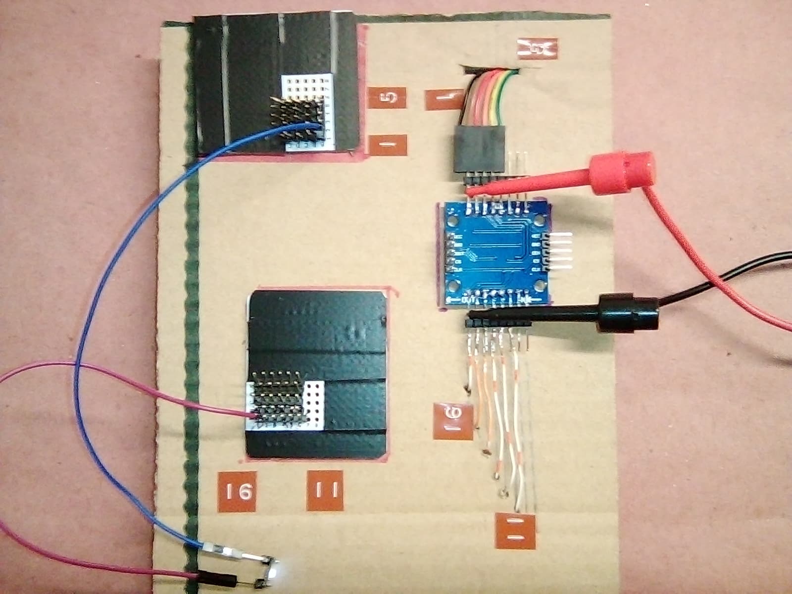
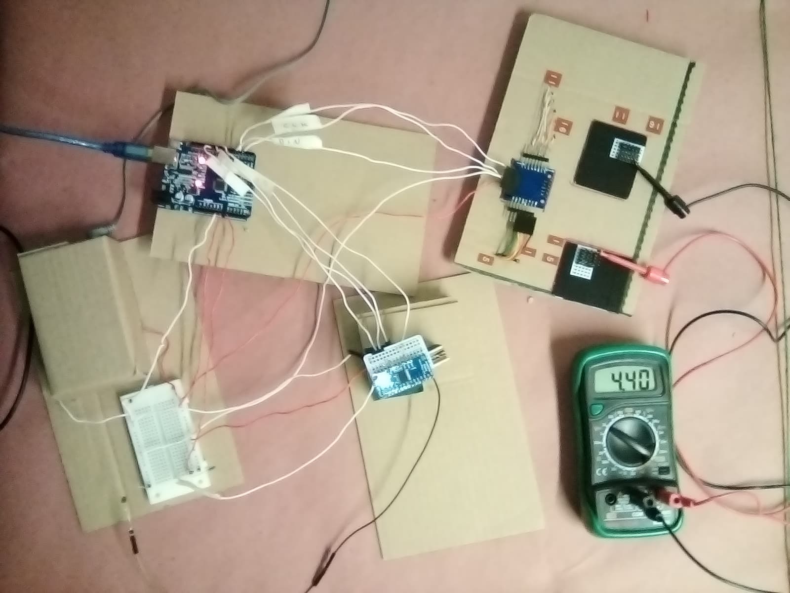
Thanks for the tips. I will try a lot of stuff Monday and through out the following weeks. I have the circuit hardware set up mostly. I will try the different sketches, and continue to learn more about everything, and present results and questions that arise.
I made the electrical connections on this system. With this I could test that the hardware components were working by using sketches specific to the different facets. I also verified to a degree that when concerted together the electrical connections were functional.
- The16-Channel multiplexor. I tested this using Adams sketch referenced above. I used an Light Dependent Resistor at a few of the channels. I was able to use this tip @ Paul_B, which was helpful, I didn't see that in the sparkfun or adafruit tutorial. It will save me 29 resistors.
- I also tested the matrix sketch using the one from a7 above in the wowki to control 1 LED. I was able to get about 5 V at the row/column I wanted. I have also read the documentation on this library. It has helped me understand the library better if anybody else is using the library but hasn't seen the page linked, its a pretty nice website that explains the library.
LedControl
One thing I think I learned is that you cant just put a number into
matrix.setLed(0, row, column, true);
for the row and column. You have to make row and column integers. That's the only way to interface with that function. This is from trying out:
matrix.setLed(0, 5, 8, true);
and it not working.
I wonder if people think that's a reasonable conclusion.
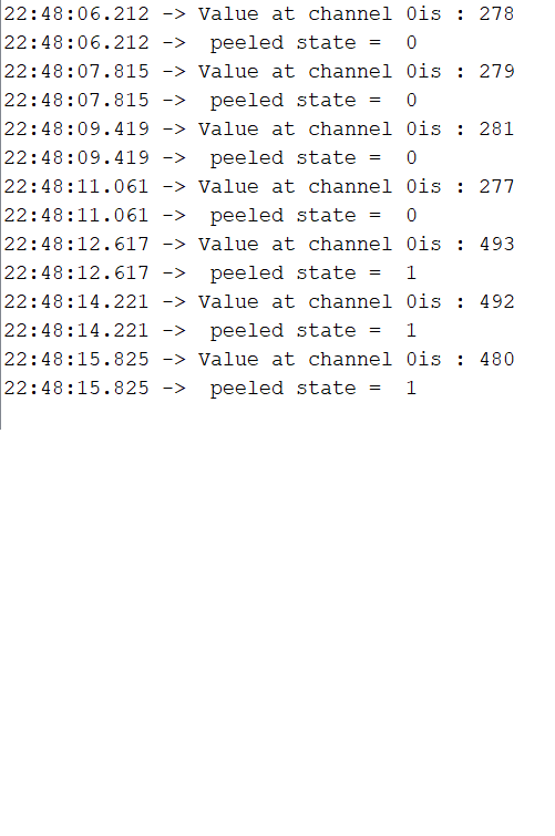
- I improved my mux/max combo sketch. I didn't make it more concise yet as per @flashko advice. I also did not change the baud rate to 115200 yet. I am still having trouble controlling the matrix with the Multiplexor. I was however able to control a single LED (the built in LED pin 13) with an LDR.
Here is the progress with the serial monitor.
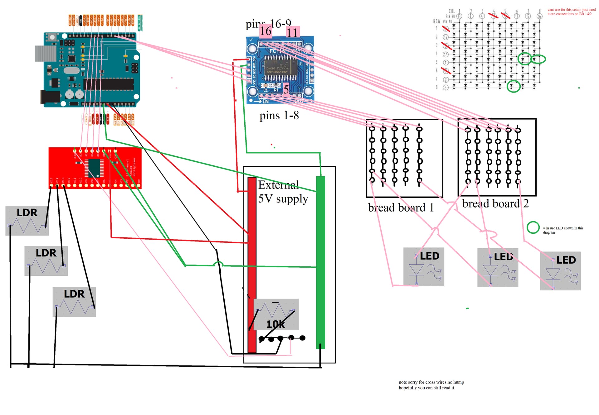
/tghe wiring diagram I made it in MSPaint. I like that I was able to draw it fairly quickly. I considered fritzing but I don't know that it would have the MAX7219 or the CD74HC4067 and I couldn't download the program b/c I don't have admin credentials.
//An integer to read a vertain channel
int readMux(int);

//Holds a data type either true or false. bool var = val. Our variable is threshold.
boolean threshold = true;

//Mux control pins
const byte s0 = 8;
const byte s1 = 9;
const byte s2 = 10;
const byte s3 = 11;

//Mux in "SIG" pin
int SIG_pin = 14;

//Max7219

#include <LedControl.h>

#define CS_PIN  4
#define CLK_PIN 3
#define DIN_PIN 5

#define MAX_SEG 1

LedControl matrix = LedControl (DIN_PIN, CLK_PIN, CS_PIN, MAX_SEG); // MAX7219


void setup ()
{
  //These lines are all setup for the Matrix


  //Switches from power saving to normal operation
  matrix.shutdown(0, false);

  //Controls the intensity  of the brightness takes value from 0-15 with setIntensity(int addr, int intensity)
  //Params:
  //  addr the address of the display to control
  //  intensity the brightness of the display.
  //  void setIntensity(int addr, int intensity);
  matrix.setIntensity(0, 7);

  //This shuts all the LEDs of
  //Params is adress
  matrix.clearDisplay(0);


  //These lines are all setup for the 16 Channel Multiplexer
  // This makes the digital pin an output
  pinMode(s0, OUTPUT);
  pinMode(s1, OUTPUT);
  pinMode(s2, OUTPUT);
  pinMode(s3, OUTPUT);

  //It has an output of either GND or 5V. This sets the default as a pulldown.
  digitalWrite(s0, LOW);
  digitalWrite(s1, LOW);
  digitalWrite(s2, LOW);
  digitalWrite(s3, LOW);

  //Here is a test LED for good measure. Also the built in LED is pin 13.
  //Pinmode for LED 13
  pinMode(13, OUTPUT);
  digitalWrite(13, LOW);


  //This sets serial data transmission rate. Sets the data rate in bits per second.
  Serial.begin(9600);
}


//I dont know the mechanics of this, I guess its where we read the anaolog value at each (i).
//86-122 if anyone can explain in a good way.
int readMux(int channel) {
  //array
  int controlPin[] = {s0, s1, s2, s3};

  int muxChannel[16][4] = {
    {0, 0, 0, 0}, //channel 0
    {1, 0, 0, 0}, //channel 1
    {0, 1, 0, 0}, //channel 2
    {1, 1, 0, 0}, //channel 3
    {0, 0, 1, 0}, //channel 4
    {1, 0, 1, 0}, //channel 5
    {0, 1, 1, 0}, //channel 6
    {1, 1, 1, 0}, //channel 7
    {0, 0, 0, 1}, //channel 8
    {1, 0, 0, 1}, //channel 9
    {0, 1, 0, 1}, //channel 10
    {1, 1, 0, 1}, //channel 11
    {0, 0, 1, 1}, //channel 12
    {1, 0, 1, 1}, //channel 13
    {0, 1, 1, 1}, //channel 14
    {1, 1, 1, 1} //channel 15
  };

  //cycle through the 4 sig
  for (int i = 0; i < 4; i ++) {
    digitalWrite(controlPin[i], muxChannel[channel][i]);
  }//close for loop

  //read the value at the SIG pin. //Read the value from the 16-channel multiplexor pin. This can only read one channel at a time.
  //and assign it to a variable.
  int analogValue = analogRead(SIG_pin);


  //Terminate a function and return a value from a function to the calling function, if desired.
  return analogValue;
}//close Adams super handy code part.


void loop() {
  //Loop through and read all 16 values...just 0 for now
  //Reports back Value at channel i is: x
  for (int i = 0; i < 1; i ++) {

    Serial.print("Value at channel ");
    Serial.print(i);
    Serial.print("is : ");
    Serial.println(readMux(i));
    Serial.print(" peeled state =  ");
    Serial.println(threshold);
    delay(1600);
  }


  //Boolean holds a data type either true or false.
  //use this way : bool varible = true or false. My variable is threshold.
  //boolean threshold = true; //(already made this a global)

  /*if (readMux(0) < 620) {
    byte row = 5;
    byte column = 8;
    threshold = true;
    matrix.setLed(0, row, column, true);
    }
    else  {

    byte row = 5;
    byte column = 8;
    threshold = false;
    matrix.setLed(0, row, column, false);

    }
  */


  // My for loop at channel 0 with LED 13
  if (readMux(0) > 300) {
    threshold = true;
    digitalWrite(13, HIGH);
  }  else {
    threshold = false;
    digitalWrite(13, LOW);
    ;
  }//close else


}//close loop


//Adams thing to retrieve value.
//switch mux to channel 15 and read the value.
// int analogValue = readMux(15);
It’s the middle of my sleep phase, but I have to tell you right away that the reason this didn’t work is that there is no column or row 8.
It would be very unusual to need to place numbers into integers in order to get a function to work. Especially if the function takes integers as arguments.
So something else must have been going on if you got something to light up by talking to an LED at 5, 8 no matter by constants or integers holding those values!
from the documentation
- row the row of the Led (0..7)
- col the column of the Led (0..7)
Take look back through your notes (!) and try to discover the path that led you to your conclusion. Mistakes are an opportunity to observe yourself going wrong…
And a very limiting conclusion, incorrect, which is why it leaped off the page when I read it.
I’ll look through the rest of your progress report L8R.
a7
Don't sidetrack yourself with that. Your diagram is OK or better, good enough.
You can simplify it a bit by using a more block level approach, but for now we can work with what you drew.
I see you commented out the section that might do something with you matrix connected LEDs, but on column 8, so no wonder you got nothing. I hope that is all and what is wrong.
You could add some more printing at the point(s) where the LEDs are actually being turnt on and off.
Also there is no shame in placing a delay(500); or even 1000 in the loop to slow things down so you can see what's going on, just remember that things will obvsly be slowed down...
Move this
delay(1600);
out of the loop, so you get all the info, then the delay instead of delay after each little piece.
At a glance, you on the verge of major success with your wise test of just three garlic bulb LDR LED combos.
a7
You progress with the project. Very good. How many LEDs and LDRs will you use in the final design? Will they work in pairs - 1 LED with 1 LDR?
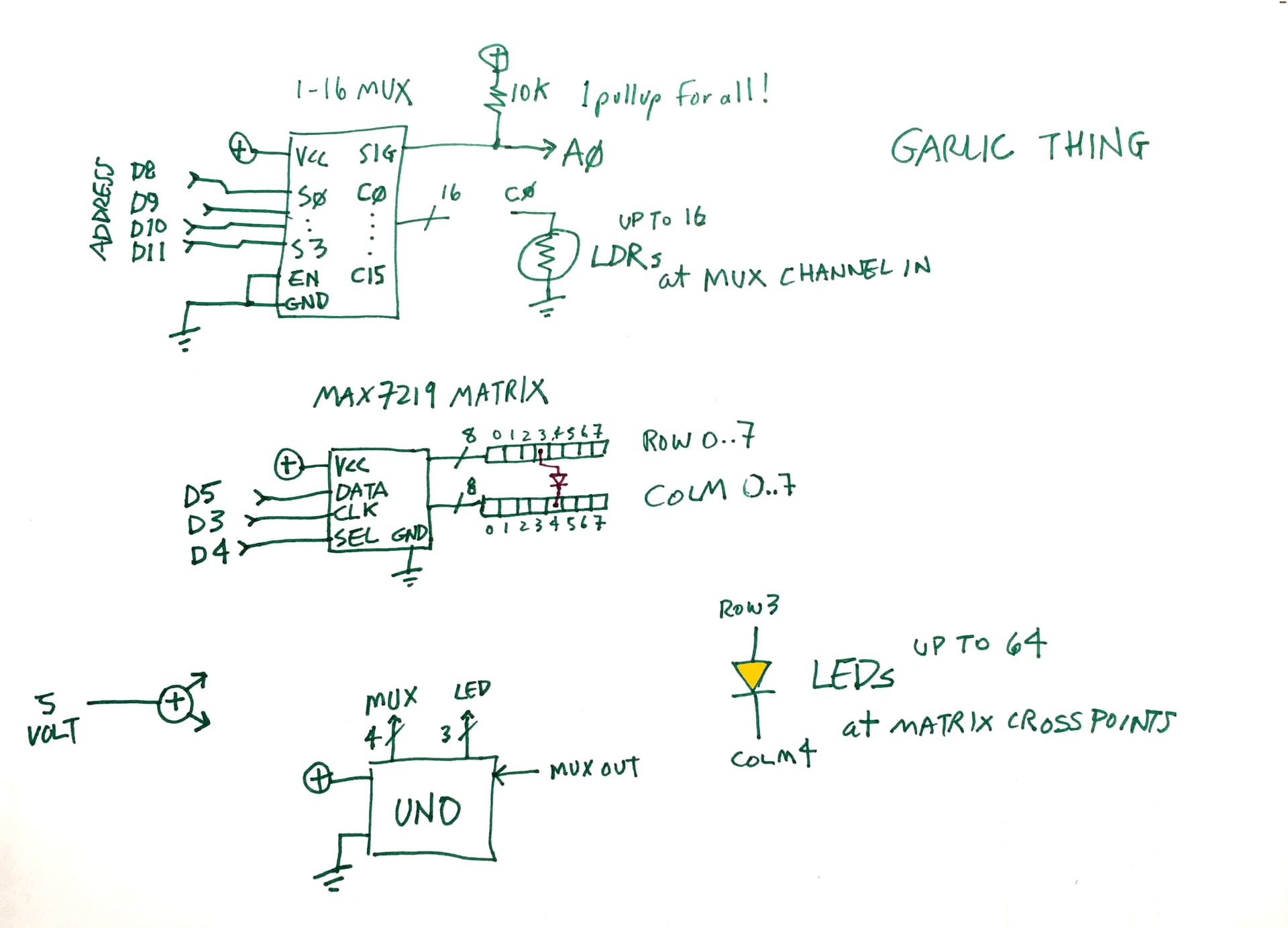
Sometimes a full schematic with every wire is necessary, sometimes important or desirable. When things get hairy, a block diagram can communicate better, esp. when coupled with readable code…
Here's a somewhat hastily hand-drawn block diagram of your circuitry, I can't say there aren't errors. Edit: the LEDs shown are backwards...
Instructables and Make Magazine go a long way to helping people do stuff, ppl who don't necessarily need to know anything.
A block diagram and program give enough info to more skilled or experienced hobbyists for them to read in rapidly to what you up to, help and/or recreate, modify or otherwise leverage your work.
a7