16 LDR-> multiplexer->nano (or uno)->MAx7219 matrix->LED

Hi,

This post has developed a lot since this intro so it would probably be better for you to start at the bottom. I want to edit it and make it more concise.

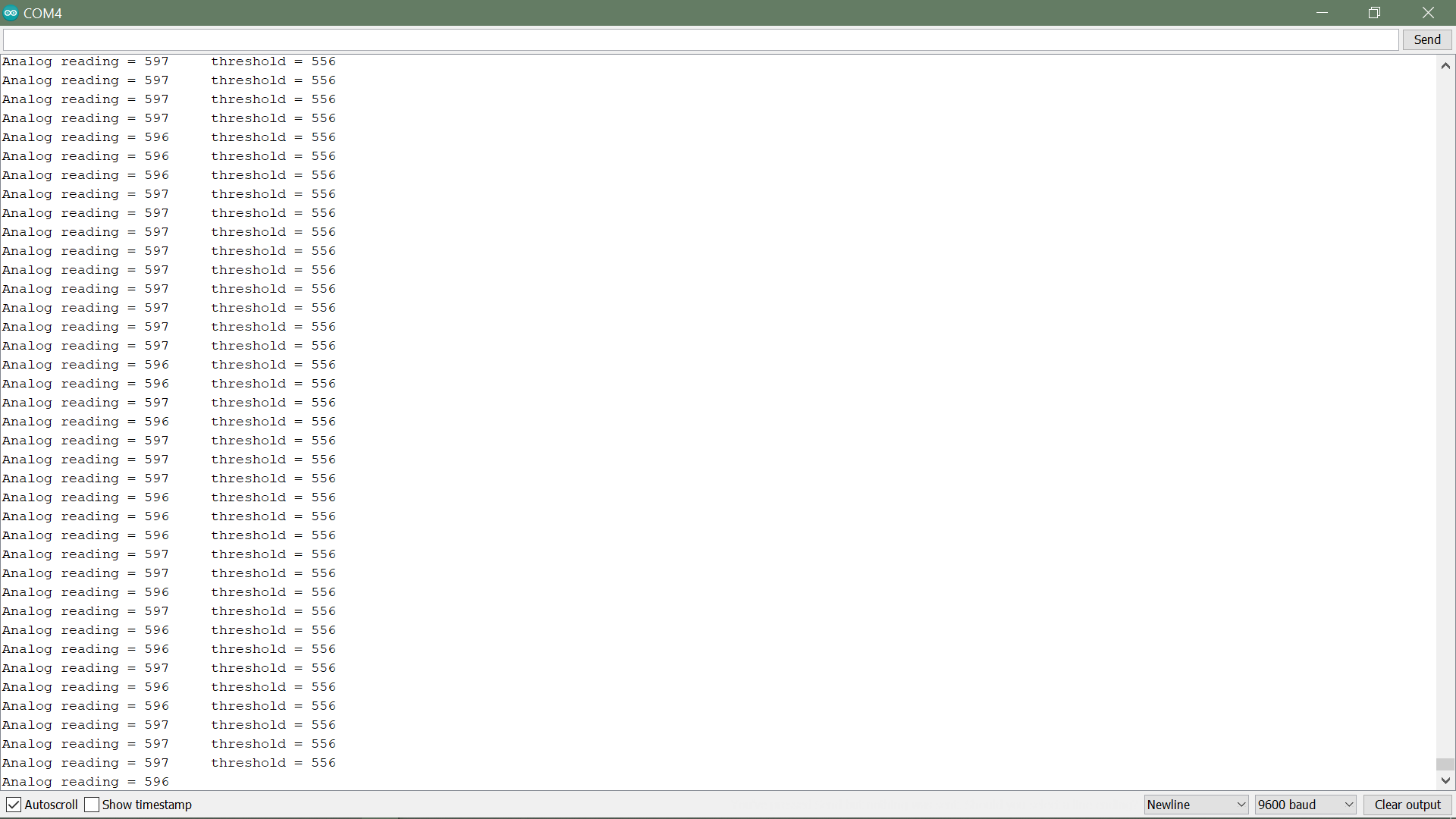
The input for this project will be the analog voltage from a voltage divider. This voltage will vary because of the variable resistor, the photoresistors. There will be 16 of these resistors.

I would like to read out only two states. Either side of some voltage value threshold. What this is value is exactly has to do with my application. Basically the photoresistor will be under a cover, mounted on a faux garlic head and I want to know when the faux peel is removed:
image

Secondly;

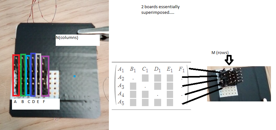
I would like to illuminate one LED per bulb peeled (LDR). It does not matter which LED goes with what.

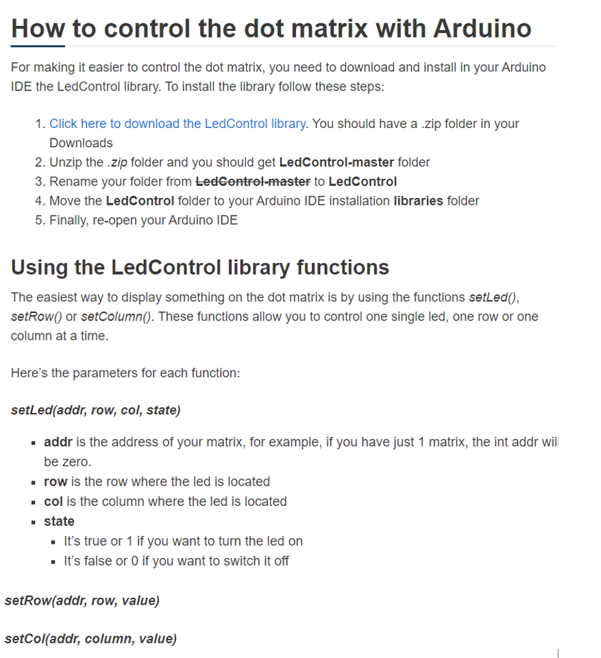
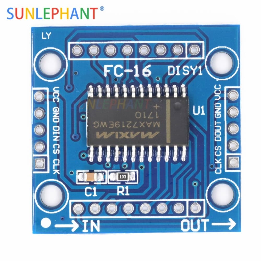
I would like to use the MAX7219 dot matrix module microcontroller. I have the unassembled module so i wont use the led tha com with it: I read about this module on the arduino playground and i will use this schematic for a basis of wiring:

in Conclusion I want to write a program that basically does like the topic says:
has an input from multiple LDRs then lights up 1 LED per LDR to indicate light or dark.
Please let me know if you would care for more details. Any advice would be awesome.

consider following which manages multiple inputs and corresponding output

// monitor a number of analog inputs

byte pinsLed   [] = { 10, 11, 12, 13 };
byte pinsPhoto [] = { A0, A1, A2, A3 };
const int Npins = sizeof (pinsPhoto);

enum { Off = HIGH, On = LOW };
char s [80];

void loop (void) {
    for (int n = 0; n < Npins; n++)  {
        int val = analogRead (pinsPhoto [n]);

        int led = Off;
        const char *p;
        if (val < 10)
            p = "Dark";
        else if (val < 200)
            p = "Dim";
        else if (val < 500)
            p = "Light";
        else if (val < 800)
            p = "Bright";
        else  {
            p   = "Very bright";
            led = On;
        }

        digitalWrite (pinsLed [n], led);

        sprintf (s, "cell %2d, %4d %s", n, val, p);
        Serial.println (s);
    }

    delay (1000);
}

void setup (void) {
    Serial.begin (9600);

    for (int n = 0; n < Npins; n++)  {
        pinMode (pinsLed [n], OUTPUT);
    }
}

hi @feltsg Not sure why you started a new thread. Ppl are gonna be "helping" you decide things you've already; there is quite a bit of info spread through your other thread:

So I have only one question.

… then lights up 1 LED per LDR


is it an LED mated to each LDR, or is it N LEDs on if N LDRs are active?

If it is not mating, do the LEDs light up in a known sequence, that is does the first LDR, no matter which, to activate illuminate LED 1, the second LDR, no matter which, lights up LED 2 &c.

Like a bar graph, even if you have them not arranged linearly? Or just at any time N LDRs are active, some (random? or?) N LEDs are illuminated.

Either is easy, it is again at the point where you need to get very descriptive, I hope you can see the ambiguity and leeway that your too brief description allows.

TBC should LDRs 3, 5, 11 and 13, for example, illuminate LEDs 3, 5, 11 and 13 OR exactly LEDs 1, 2, 3 and 4 OR any four LEDs by logic or random like 4, 6, 10 and 17?

May we assume that the LEDs are extinguished as LDRs go dark? In reverse order of how they were illuminated?

Code is cruel and you will get exactly what you program, which until you say exactly what you want may not be what you expected.

HTH

a7

Hello,
Sorry for the delayed response. I was swamped with work. I started a new topic so that I could post it in the programming questions topic, and that so it would be towards the top if people were sorting the post by most recent. I also wanted to make the post more concise, and I did not want to show the work I was doing with molding and casting if it wasn't relevant, since it is personal. I did mention this at the top of the thread and offered to share the link of others were interested. I see that you have also included a link to that post.

I was planning on replying to your questions but I had not the chance. In response matching LDR to LED. I see you have a lot of ideas and expertise on this. The options you described I was not even aware of so I'm glad you mentioned them.

Best wishes,

No worries, we here.

Reading your description again carefully and my questions as well leaves me confused bewildered, haha, so I hope that makes clear my main point: that you will have to go into some detail before coding this or be prepared for surprise outcomes.

In fact you may discover more about what you want to do really when you have happy accidents.

You should, if no one said already, make sure the sensors and the LEDs are responding correctly with the simplest test program(s) possible.

With these little systems getting things working all at once can be, um, time consuming.

CU

a7

OK, let’s see… you mean each garlic pod sensor LDR will be mated to a particular LED.

When LDR X has enough light on it, LED X should go on.

Wherever they are mounted physically, each LDR is logically linked to one LED.

Imma risk going off now, perhaps the shoe elves who are now waking up will grab this; the code should be very simple, it will be adjusting the threshold of “enough light” that will probably take more time.

Speaking of which, do you have control over the ambient light, dare we hope at least it is constant in a given installation?

A slight addition might be one more analog input with a potentiometer to adjust the trigger point.

And I was going to say what about 16 LDRs, but I see in your original thread (!) that you will be using a multiplexer module or two - have you found any examples code for that? or very hard, but it is always good to be basing your work off something simple and known to work.

The code in this thread is just using arrays to 4x in a straight ahead way to duplicate the function of the 1x from the code in your other thread. Again, (!). :wink:

a7

I just got this bit of advice from this tutorial regarding the matrix. That's a good idea to have a potentiometer to adjust the threshold.

Use this circuit hastily scribbled diagram

and the code below to see what kind of numbers your LDR will give and how the threshold idea might work.

There is nothing very critical about the resistor values; these worked well for the random LDR I found. Maybe review this in case you don't make this work right away.

/* please put some text you'll search for one day here */
 
# define photocellPin A0	// the LDR and pulldown are connected to a0
# define thresholdPin A1	// the threshold pot is on A1

# define myLED	9			// an LED and series resistor on output 9
 
void setup(void) {
	Serial.begin(9600);

	 Serial.println("hello LDR LED POT test");

    pinMode(myLED, OUTPUT);
}
 
void loop(void) {

	int threshold = analogRead(thresholdPin);

	Serial.print("     threshold = ");
	Serial.println(threshold);

	
	int photocellReading = analogRead(photocellPin);
	
	Serial.print("Analog reading = ");
	Serial.print(photocellReading);

	if (photocellReading > threshold)
		digitalWrite(myLED, HIGH);
	else
		digitalWrite(myLED, LOW);
 
	delay(100);
}

Hi,
Building this circuit, could you clarify this connection:
111

That's a 10K potentiometer, one end to Vcc, the other end to ground and the wiper (middle contact) fed to an analog input.

That makes a voltage divider, and allows you to sorta "enter" a number by turning the knob, giving you 0..1023 as you move it from one extreme to the other.

That is read in the code and used as a value "threshold" to compare to the reading from the LDR, which is also a voltage divider, read by another analog input and giving you a value that varies from light to dark, but does not go from 0..1023 but from smaller number in that range to a larger number in that range depending on the light falling on it.

I probably should have used another resistor in the LDR circuit 4K7 in series on the line going to A0. It affords some protection against wiring mistakes and so forth.

Someone who knows more will say why or why not; I think you can "get away" without it, as you might do without the one between the pot and A1, I am just not a "get away" with type, and I am a "makes stupid wiring mistakes sometimes" type. :wink:

And 4K7 is not critical, anything from2K2 to 22K would work without difference.

See the numbers fly in the serial monitor and get an idea of just how the LDR will show up when converted to digital offa A0.

BTW I think you have 16 garlic bulbs; there are 16-1 multiplexer chips (or modules) available. If you already have 8-1 units you want to use, no problem it would be easy to just use two analog inputs, each taking half the LDRs... and warp that up in a function so it's easy to use conceptually.

FWIW I think if you want to learn about and don't know anything yet, functions and arrays will be useful to making coding easier - easier to write, get working, modify and for anyone who does, even you tomorrow or next week, read.

a7

Ok thanks I didn't realize that was a potentiometer. Is that code ready to compile or do I need to change something. I first I thought I might need to put in a threshold value, but I guess that's coming from A1(the pot).

So answering my own question yes the code could be compiled(hopefully that's the right word).

So to recap, one has a voltage reading from the Photoresistor voltage divider at A0. Then the potentiometer adjsut the threshold. Which is to say the value of which on either side (IF, ElSE) led turns on.

That’s exactly right. I tried to do as little else as possible, no fancy tricks, just try reading the code, step through it.

I might have taken an extra moment to ‘splain it, it should make direct sense I hope.

a7


Okay, feels like progress, this preliminary example/test worked!
Thanks

This is what I am working on for the matrix controlling the LED
I am trying to wire the schematic shown. One breadboard is rows, the other is columns, Each pin, would be an entry in that row/column. So a particular entry would have one connection to a pin on the column board, and another connection to a pin on the row board. Its a 6x5 matrix as of now. Any tips/advice are always welcome


Only to start small, and I mean very. Small.

Goal: Put one LED at a random crosspoint, say column 3 and row 7, turn it on and off by program.

In that process you will

... need to install a (the?) MAX7219 library

... discover how to declare your particular display control module

... wire it to the necessary i/o pins on you Arduino

... find the library function that can turn on and off that one LED

al without messing with too many wires and things that are at this point too soon worried about, confused by, wired incorrectly &c.

Which makes me ask, which exact MAX7219 board do you have?

a7

I appologize but i have not read all the posts in the topic. I don't know if you mean that LDRs are slow and MAX7219 controls the LEDs by multiplexing and with a scan rate of 800 Hz - the diodes flickering. Just by lighting a diode and just reading the LDR detection may not work. Usualy LDR is sensitive to green light. If you uses red LED maybe is also bad idea.

https://datasheets.maximintegrated.com/en/ds/MAX7219-MAX7221.pdf

'Page 2 - Display Scan Rate fOSC 8 digits scanned 500 800 1300 Hz'

'Response time of 2 – 50 ms.'

'The common CdS (cadmium sulfide) LDRs have peak spectral response at about 550 nm which is the green region of the visible spectrum. Note that if illuminating the LDR with an LED that a red LED might give only about 30% of the response of a green LED on the same current.'

Just saying.


al without messing with too many wires and things that are at this point too soon worried about, confused by, wired incorrectly &c.

I think your probably referring to the bread board with the Photoresitor...I could clean that up just a prototype, I will solder things for the final assembly and use less of those whisker wires.

Regarding the Matrix you see the underside of the module, here is a detail of the concept:

here's a pic of the board IC and datasheet for the matrix. I am also finding the linked tutorials helpful (listed already above:
"Guide for 8x8 Dot Matrix MAX7219 with Arduino | Random Nerd Tutorials") ,

and

(if any reader is curious about this info its here but of course read what you wish, say as like)

I will also includ the datasheet for the matrix which gives some detail regarding how the component works regarding the actual digital signal. I have not reviewed this so closely yet so I cant give a good overview of what information it holds.
MAX7219-MAX7221.pdf (491.3 KB)

It is my understanding that the OP wants an LED to come on when a corresponding LDR is exposed to ambient light. So no feedback, no worries about speed, flickering or wavelengths.

a7

No issues with flickering. Maybe you heard flickering because they were on and off. That was intended. Lately I am trying to approach the issue of controlling individual LED using this Matrix module. Regarding this I would say 2 things stick out in my mind right now;just briefly describing these challenges;

  • writing a program to do the stuff I have been trying to describe in this topic

  • wiring the matrix to individual LED instead of using the dot display that comes with it.

Maybe this code help.

In the code no LDR reading, just on and off LED after LED.