Hello,
For a project I'd like to drive 7xSG90 servo's using arduino uno. I bought a shield off a chinese supplier (First I looked at an electronics supplier online, they had a 3rd party board, I searched through chinese suppliers and found the exact same one, via's in the same place and all, but for 1/5th of the price. I generally have good experiences with chinese suppliers so I took the risk) but I can't seem to be able to drive a single servo using it (Servo's are also chinese supplier).
Setup:
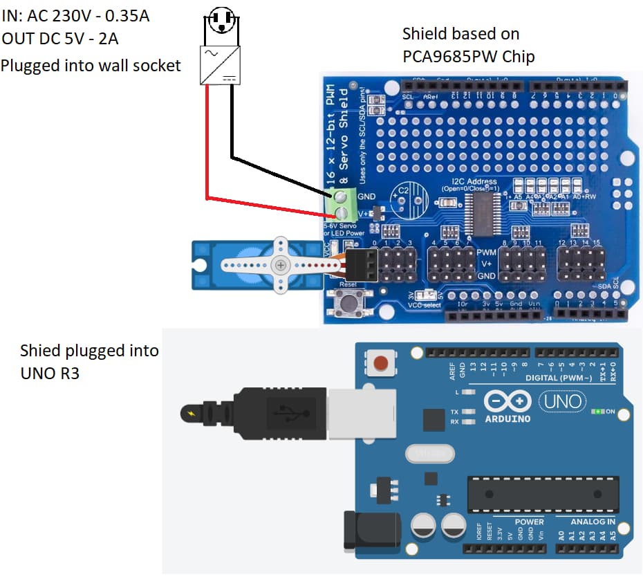
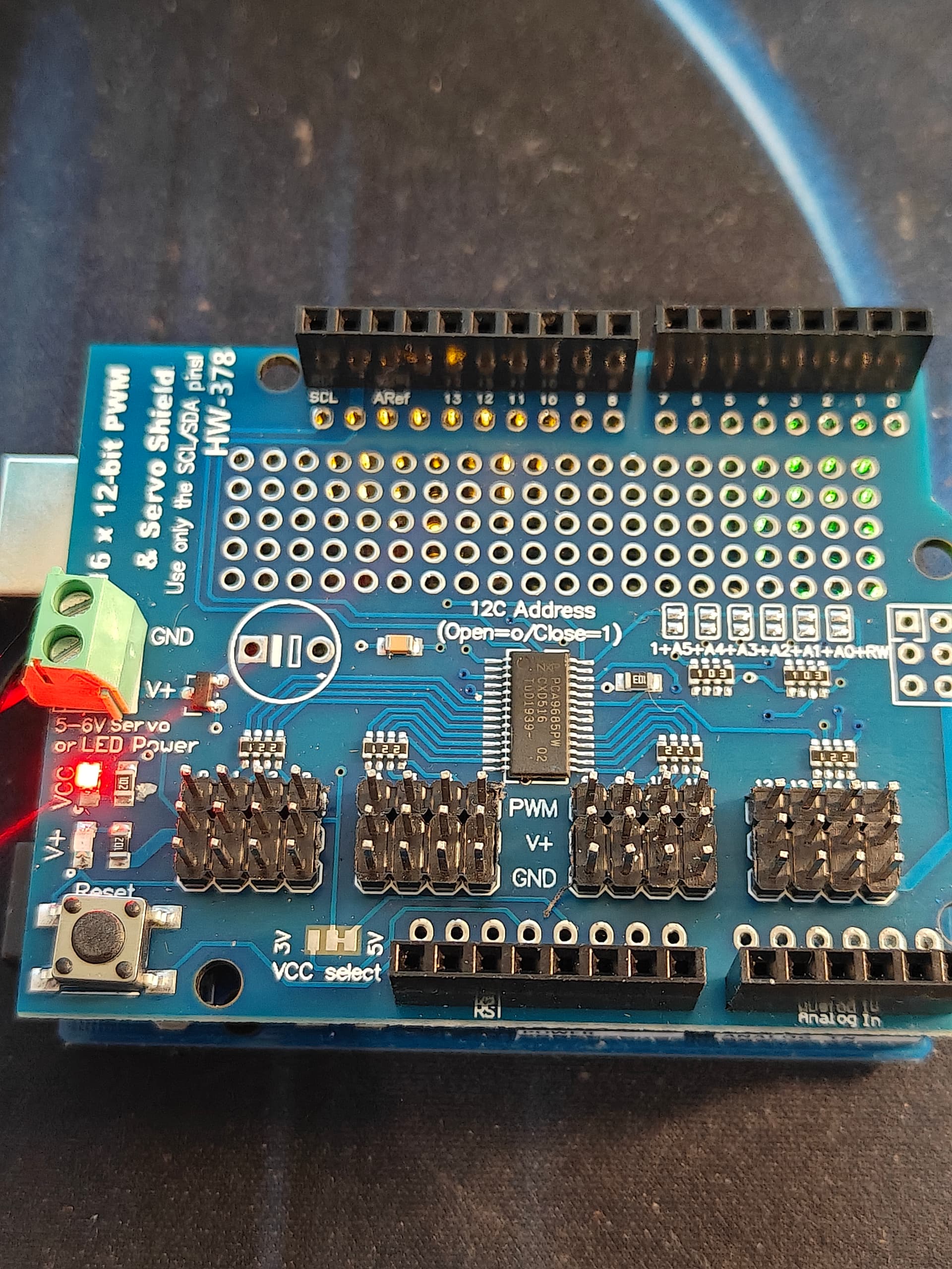
- 16x12bit PWM servo shield (HW-378, it seems to be using the PCA9685PW chip)
- SG90 attached to 0 (Yellow to PWM, Red to V+, Brown to GND)
- Elegoo uno R3 powered through USB
- Samsung Travel adapter 5V 2A as power supply to Servo shield V+/GND
- PWM_servo_test example sketch from adafruit PWM Servo Driver Library.
What happens:
When I plug the servo in, I heard gears and then it only clicks every second or so. It makes me think it's hitting the limiter: but the program should drive it back and forth. Now it makes no sound at all anymore (confirmed Servo's still work, as explained below).
I tried and confirmed this:
- Servo's work when using the Elegoo servo example sketch: supplying 5V off the board and using pin 9 to momentarily rotate the servo (using the servo.h library)
- Measuring the V+ & GND: it gives 5.10V on all the pins (both input and the pins you plug the servo in.
- Adjusting the Wire.setCLK. from 400kHz to 4kHz, it changed nothing.
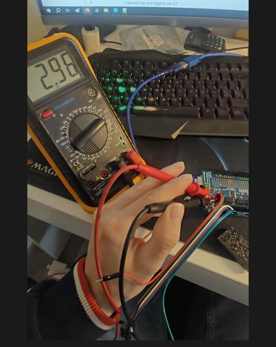
- Measuring the PWM towards GND using multimeter on DC, which gives and indication if there is a signal or not, but not more or less then that: it gives alternativly 0 and a rising value (highest value measured was 2.96V DC).
Here is the example I'm rocking now:
// https://learn.adafruit.com/adafruit-16-channel-pwm-slash-servo-shield/using-the-adafruit-library

/***************************************************
  This is an example for our Adafruit 16-channel PWM & Servo driver
  GPIO test - this will set a pin high/low

  Pick one up today in the adafruit shop!
  ------> http://www.adafruit.com/products/815

  These drivers use I2C to communicate, 2 pins are required to
  interface.

  Adafruit invests time and resources providing this open source code,
  please support Adafruit and open-source hardware by purchasing
  products from Adafruit!

  Written by Limor Fried/Ladyada for Adafruit Industries.
  BSD license, all text above must be included in any redistribution
 ****************************************************/

#include <Wire.h>
#include <Adafruit_PWMServoDriver.h>

// called this way, it uses the default address 0x40
Adafruit_PWMServoDriver pwm = Adafruit_PWMServoDriver();
// you can also call it with a different address you want
//Adafruit_PWMServoDriver pwm = Adafruit_PWMServoDriver(0x41);
// you can also call it with a different address and I2C interface
//Adafruit_PWMServoDriver pwm = Adafruit_PWMServoDriver(0x40, Wire);

void setup() {
  Serial.begin(9600);
  Serial.println("GPIO test!");

  pwm.begin();
  pwm.setPWMFreq(1000);  // Set to whatever you like, we don't use it in this demo!

  // if you want to really speed stuff up, you can go into 'fast 400khz I2C' mode
  // some i2c devices dont like this so much so if you're sharing the bus, watch
  // out for this!
  Wire.setClock(4000);
}

void loop() {
  // Drive each pin in a 'wave'
  for (uint8_t pin=0; pin<16; pin++) {
    pwm.setPWM(pin, 4096, 0);       // turns pin fully on
    delay(100);
    pwm.setPWM(pin, 0, 4096);       // turns pin fully off
  }
}
Can you guys help me locating the issue? I have no experience using I2C Is there anything left to check? I do not have access to an oscilloscope.
(edited a variable that I miscalled)
(edited wrong chip nr.)