I have tons of leftover LEDs so I thought I just could have some fun and hook them up in a 16 by 16 LED Matrix. Here's the thing: Since this is a 'just for fun' project' I am planning to use as much of the stuff I still have laying around.
256 LEDs do take some effort to be controlled so I was wondering about what could possibly be the best way to do it. I have the following ICs at hand: 74HC595 Shift Registers, ULN2803 Darlington Drivers, MAX7219 LED Drivers. Maybe someone of you could give me some advice.
Greetings,
Vulpecula
P.S.: All the LEDs are of the same kind, so no worries about different voltages/currents.
4 max7219 would be the most obvious and simplest answer. Make 4 8x8 matrices that can be placed immediately next to each other and use one max7219 for each. Daisy-chain the max7219 data In & out pins and share the same clock and latch pins between the 4 chips.
Another option would be 2 74hc595 sourcing current to the common anodes and 2 more 74hc595 sinking current from the common cathodes via 2 uln2803 chips. Disadvantages compared to the first solution: 2 more chips; lower brightness due to current limitations of 74hc595 combined with 1:16 multiplex; need to implement multiplexing in the Aruino sketch; more current limiting resistors needed.
I already guessed, that the MAX7219 would be the best way, but I have some difficulties in understanding the way how the actual ICs and the MAX7219 library work. I know how the ICs work, yes, but my problem is that I want to setup a 16 by 16 matrix but most of the tutorials and examples of daisy chaining several MAX7219 won't cover that. Instead of that they usually cover 8 by 16,24,etc matrices.
Since I am relatively new to programming the Arduino* I thought that I could set up something to get a little more into it by just doing something. I've already done some things with 8x8 matrices and the MAX7219 but that was just tinkering around (mostly with self-modified code from tutorials). I've seen several videos of LED matrices and thought that this might be something nice to do. Once I fully understand how to program and/or control that matrix I might be able to extend that by showing actual information on that matrix (e.g. a special icon whenever i've got new mail) and stuff like moving sprites, etc.
I know my way around electronic circuits but the µController side is pretty new to me.
Edit: So this is how I'll put this together then...:
Yes that looks ok, except that those Iset resistors should be around 10K, not 1K. Add 0.1uF near the power pins of each max7219 and a 10uF around each max7219.
To minimize power-supply ripple due to the peak digit driver currents, connect a 10µF electrolytic and a 0.1µF ceramic capacitor between V+ and GND as close to the device as possible.
So I assume the capacitors need to be placed parallel to the VCC, right?
Edit: Corrected diagram. The 1k resistor was actually a copy&paste mistake
4 MAX7219 can be controlled with parola library, or you can roll your own.
After setting up the 5 control registers (scan limit to All, brightness to midway, display test, decode mode off, and normal mode on), then you're just writing data into 8 registers on each part.
Lets assume you have 4 discrete chip selects so update can be done faster:
You can have a 16x16 array
int dataArray[16];
that you manipulate and then send to the 4 parts:
// upper left half
digitalWrite (sspin1, LOW);
for (x=0 x<8; x=x+1){
SPI.transfer (x+1); // data register addresses are 1 to 8, but array index is 0 to 15
SPI.transfer(highByte(dataArray[x]));
}
// upper right half
digitalWrite (sspin2, LOW);
for (x=0 x<8; x=x+1){
SPI.transfer (x+1); // data register addresses are 1 to 8, but array index is 0 to 15
SPI.transfer(lowByte(dataArray[x]));
}
// lower left half
digitalWrite (sspin3, LOW);
for (x=8 x<16; x=x+1){
SPI.transfer (x-7); // data register addresses are 1 to 8, but array index is 0 to 15
SPI.transfer(highByte(dataArray[x]));
}
// lower right half
digitalWrite (sspin4, LOW);
for (x=8 x<16; x=x+1){
SPI.transfer (x-7); // data register addresses are 1 to 8, but array index is 0 to 15
SPI.transfer(lowByte(dataArray[x]));
}
with array set up like this for example
0 1 2 3 4 5 6 7 8 9 10 11 12 13 14 15
1
2
3
4
5
6
7
8
9
10
11
12
13
14
15
Vulpecula:
So I assume the capacitors need to be placed parallel to the VCC, right?
Not sure what you mean by "parallel".
The PCB needs to be designed so that the total length of the tracks between capacitors and the Vcc and Gnd terminals of the MAX7219 plus the leads on the capacitors themselves is minimised. This is somewhat tricky if the corresponding pins of the IC are on opposite sides, one way to achieve this is to have the traces coming together under the IC, running out to one end of the IC and the two capacitors are placed there. Design is of course, vastly easier if you use double-sided PCB.
About the caps: I was just wondering why there had to be two caps with different characteristics. As far as I understand this, multiplexed LED matrices tend to have a fast fluctuation of their current (depending on the changes within the matrix). The 0.1µF cap 'filters' out the fast fluctuations while the 10µF cap has a little delay (due to higher inductance). Together they reduce under- and overshoot at Vcc, created by the current changes and the inductance of the lead. No need to get hung up on this but I really wanted to understand this circuit.
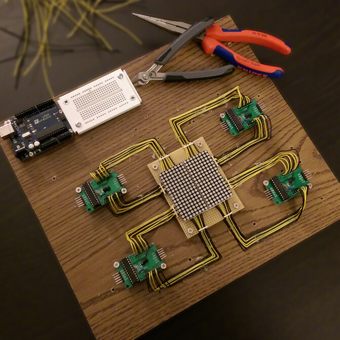
About the matrix: I didn't have much time to go deeper into this but this weekend I decided to sacrifice some time and some parts. I quickly slapped together some kind of prototype (yeah, it's not really pretty) which I can use to test some code later.
FYI: I had to solder the matrices. I bought some cheap-a** sets from amazon only to realize that the matrices wouldn't fit on the sockets of the boards. Didn't matter though, since I bought those sets just for the MAX7219 chip. One set (chip, board, matrix) did cost me excatly the same as a single chip at that time so I didn't care.
@CrossRoads: I like your array idea. A two-dimensional array would be just fine, since it would be easy to come up with an algorithm that is able to handle different sizes of matrices. But for the rest of your reply... I see words but they make no sense to me...
Vulpecula:
As far as I understand this, multiplexed LED matrices tend to have a fast fluctuation of their current (depending on the changes within the matrix). The 0.1µF cap 'filters' out the fast fluctuations while the 10µF cap has a little delay (due to higher inductance). Together they reduce under- and overshoot at Vcc, created by the current changes and the inductance of the lead.
The MAX7219 is of course, continuously scanning the matrix and so generating fluctuations unless each column scanned happens to contain the same data, not to be confused with the occasional changes when you write different data into the registers. And in any case it is performing PWM, so the full current is switching unless you have selected maximum intensity.
Vulpecula:
I quickly slapped together some kind of prototype (yeah, it's not really pretty) which I can use to test some code later.
Looks rather neat to me, so far.
Vulpecula:
I bought some cheap-a** sets from Amazon only to realise that the matrices wouldn't fit on the sockets of the boards.
I find that surprising. In what way would they not fit?
Paul__B:
I find that surprising. In what way would they not fit?
The socket-rows (not the spacing between the sockets) are just a little too close together. But still too much to fit the matrix by bending some pins. Now that I think of it, I could have tilted the socket rows (with the help of a soldering iron) and MAYBE they might have fit. Who cares, it's just cheap crap from China.
Vulpecula:
The socket-rows (not the spacing between the sockets) are just a little too close together.
Interesting!
You may have struck it lucky!
The LED arrays come in 3mm and 5 mm versions. The boards are designed for the 3 mm version, but the rows are wider on the 5 mm arrays and it looks like that is what you have been supplied. It looks suspiciously like you have been "Super-sized"!
Might be... All I cared for were the MAX drivers anyway.
Now... PaulRB said I won't need special libraries to control the MAX7219 / the matrices. Are there actually any resources online that I could read my way through to learn about this?
The function send7219() is used to send pairs of bytes to the chip. In your case you will have 4 chips. Have you decided if you will connect them in a chain or with in parrallel with 4 separate load/latch lines?
Thank you for that. I will definitely have a look at that.
PaulRB:
Have you decided if you will connect them in a chain or with in parrallel with 4 separate load/latch lines?
Actually, what would be the best way?
[A random guess appears...]
Maybe it will be better to just daisy-chain the four chips because programming might become easier that way. (Although I actually do have enough pins on my Arduino Mega.)
I just wish I could start coding right away but there are several math-exams coming up and I want to concentrate on those first.