Your code is too faint to read. Perhaps you could try pressing the keys a bit harder.
Try checking your four data lines. My guess is that you have a problem with one or more of them.
Be aware that there is a problem with how the LiquidCrystal library deals with the cursor positioning on lines 3 and 4 of the 16x4 display. They may get it fixed in a future release, possibly before 2020.
You can run it with no problems except that, without some minimal additional code, the characters on the last two lines will be indented by several positions.
Well, i soldered everything on both 16x2 and 16x4, still nothing. I did briefly see hello world in the 16x2 and then it faded away. The 16x4 just scrolls through all the characters. Im thinking of ordering one from sparkfun or another credited site becuase ive got these all screwed up.
The picture of the code is too large to post but its the same as the "hello world example".
There's no 'picture' involved. Copy the code from your Arduino IDE screen and paste it into your message reply. Then highlight that code and click on the 'code' button </>.
void setup() {
// set up the LCD's number of columns and rows:
lcd.begin(16, 4);
// Print a message to the LCD.
lcd.print("hello, world!");
}
void loop() {
// set the cursor to column 0, line 1
// (note: line 1 is the second row, since counting begins with 0):
lcd.setCursor(0, 1);
// print the number of seconds since reset:
lcd.print(millis()/1000);
}
Its just copied and pasted bc I dont have internet at home.
I have a felling that the 16x2 has either a signal problem or I damaged it somehow while learning how to hook it up. I have examined this circuit over 3 different days and it has clean solder joints.
I fell like the 16x4 is not compatable somehow. The contrast works and it displays, it just scrolls through all its characters.
Try the following code with both devices. You can (but don't have to) change the lcd.begin(...); statement since we aren't trying to position the cursor.
#include <LiquidCrystal.h>

//LiquidCrystal lcd(rs,en,d4,d5,d6,d7);
  LiquidCrystal lcd(12, 11, 5, 4, 3, 2);       // put your pin numbers here

void setup()
  {
    lcd.begin(20, 4);                          // put your LCD parameters here
    for (char i=47; i<127; i++)                // send 80 consecutive displayable characters to the LCD
      {
        lcd.print(i);
        delay(100);                            // this delay allows you to observe the addressing sequence
      }
  }


void loop()
  {
  }
Don
P.S. Do you see what the 'code tags do? Here's the same code without them:
#include <LiquidCrystal.h>
//LiquidCrystal lcd(rs,en,d4,d5,d6,d7);
LiquidCrystal lcd(12, 11, 5, 4, 3, 2); // put your pin numbers here
void setup()
{
lcd.begin(20, 4); // put your LCD parameters here
for (char i=47; i<127; i++) // send 80 consecutive displayable characters to the LCD
{
lcd.print(i);
delay(100); // this delay allows you to observe the addressing sequence
}
}
All that code did was verify that your device is connected properly and is functioning properly. This means that the strange results you previously had were likely based on the program code, not on the hardware.
I would suggest that you try this program next with your 16x2 display:
include <LiquidCrystal.h>

//LiquidCrystal lcd(RS, E, D4, D5, D6, D7);
LiquidCrystal lcd(7, 8, 9, 10, 11, 12);      // put your pin numbers here

void setup()
  {
  lcd.begin(16, 2);                          // put your LCD parameters here
  lcd.print("hello, world!");
  lcd.setCursor(0,1);
  lcd.print("it works!");
  }

void loop()
  {
  }
For your 16x4 display change the lcd.begin(...) statement and add the following code to setup()
  lcd.setCursor(0,2);
  lcd.print("this is line 3");
  lcd.setCursor(0,3);
  lcd.print("this is line 4");
You should see lines 3 and 4 offset by a few characters for the reasons I mentioned previously and with the fix in my previous link.
When all this works then try the liquid crystal 'hello world' example code again.
I can't figure out how it could work properly for the code in reply #10 and then give the results shown in your image with the code in reply #12.
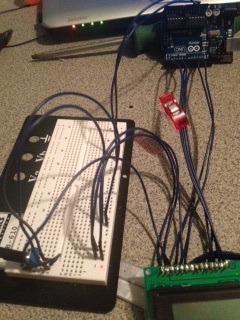
We need to see a clear picture of the entire setup where we can unambiguously follow each wire from one end to the other and also see the output on the display. We also need a copy and paste version of the code that resulted in the display in the photo.
Well here is the pic of setup the best i could do. Sorry for using all blue jumpers.
I have D0-D3 soldered but are not in use.
Pin 3 is going to wiper on pot.
Pin 5 R/W is going to ground.
All others should be assigned correctly as code states.
Once i get internet to laptop ill post entire code.