Thank you... makes sense.. and yes I meant arrows lol. Thank you!
What does "cit" mean?
"You would cit that trace and solder the adjacent 2"
That was a typo. I have edited it to read "cut." That means you would use an Xacto knife or such and cut through it so that it no longer makes electrical contact.

Thank you so much!
Thank you for this sir!
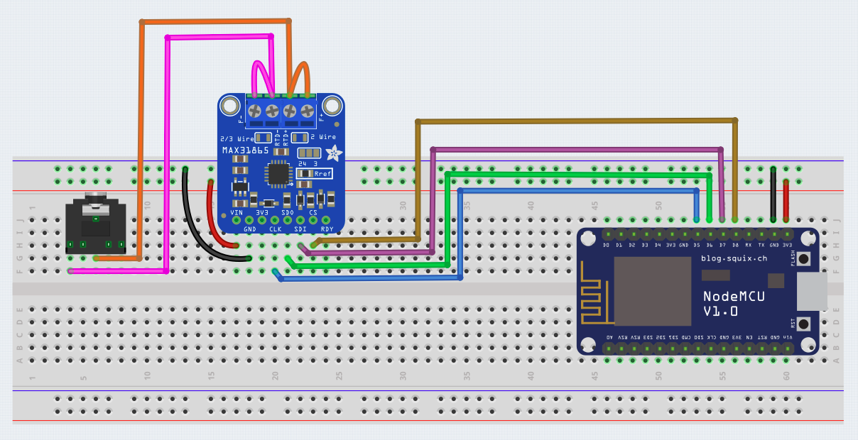
The MAX finally came in and I was able to get everything wired up, but I have either wired wrong or not updating the code from the example libraries properly.
Below are some pictures of my wiring. Hopefully the angles are ok, and the output. and below that is the code.


/***************************************************
  This is a library for the Adafruit PT100/P1000 RTD Sensor w/MAX31865

  Designed specifically to work with the Adafruit RTD Sensor
  ----> https://www.adafruit.com/products/3328

  This sensor uses SPI to communicate, 4 pins are required to
  interface
  Adafruit invests time and resources providing this open source code,
  please support Adafruit and open-source hardware by purchasing
  products from Adafruit!

  Written by Limor Fried/Ladyada for Adafruit Industries.
  BSD license, all text above must be included in any redistribution
 ****************************************************/

#include <Adafruit_MAX31865.h>

// Use software SPI: CS, DI, DO, CLK
Adafruit_MAX31865 thermo = Adafruit_MAX31865(6, 5, 3, 2);
// use hardware SPI, just pass in the CS pin
//Adafruit_MAX31865 thermo = Adafruit_MAX31865(10);

// The value of the Rref resistor. Use 430.0 for PT100 and 4300.0 for PT1000
#define RREF      4300.0
// The 'nominal' 0-degrees-C resistance of the sensor
// 100.0 for PT100, 1000.0 for PT1000
#define RNOMINAL  1000.0

void setup() {
  Serial.begin(9600);
  Serial.println("Adafruit MAX31865 PT1000 Sensor Test!");

  thermo.begin(MAX31865_2WIRE);  // set to 2WIRE or 4WIRE as necessary
}


void loop() {
  uint16_t rtd = thermo.readRTD();

  Serial.print("RTD value: "); Serial.println(rtd);
  float ratio = rtd;
  ratio /= 32768;
  Serial.print("Ratio = "); Serial.println(ratio,8);
  Serial.print("Resistance = "); Serial.println(RREF*ratio,8);
  Serial.print("Temperature = "); Serial.println(thermo.temperature(RNOMINAL, RREF));

  // Check and print any faults
  uint8_t fault = thermo.readFault();
  if (fault) {
    Serial.print("Fault 0x"); Serial.println(fault, HEX);
    if (fault & MAX31865_FAULT_HIGHTHRESH) {
      Serial.println("RTD High Threshold");
    }
    if (fault & MAX31865_FAULT_LOWTHRESH) {
      Serial.println("RTD Low Threshold");
    }
    if (fault & MAX31865_FAULT_REFINLOW) {
      Serial.println("REFIN- > 0.85 x Bias");
    }
    if (fault & MAX31865_FAULT_REFINHIGH) {
      Serial.println("REFIN- < 0.85 x Bias - FORCE- open");
    }
    if (fault & MAX31865_FAULT_RTDINLOW) {
      Serial.println("RTDIN- < 0.85 x Bias - FORCE- open");
    }
    if (fault & MAX31865_FAULT_OVUV) {
      Serial.println("Under/Over voltage");
    }
    thermo.clearFault();
  }
  Serial.println("TEST");
  Serial.println();
  delay(1000);
}
/***************************************************
  This is a library for the Adafruit PT100/P1000 RTD Sensor w/MAX31865

  Designed specifically to work with the Adafruit RTD Sensor
  ----> https://www.adafruit.com/products/3328

  This sensor uses SPI to communicate, 4 pins are required to
  interface

  Written by Limor Fried/Ladyada for Adafruit Industries.
  BSD license, all text above must be included in any redistribution

 ****************************************************/

//-----------------------------------------------------------
// ******** Modified for the ESP8266 and PT1000 ********* JIM

#include <Adafruit_MAX31865.h>

// Use software SPI: CS, DI, DO, CLK
// Adafruit_MAX31865 thermo = Adafruit_MAX31865(10, 11, 12, 13);
// Use hardware SPI, just pass in the CS pin
Adafruit_MAX31865 thermo = Adafruit_MAX31865(15);

// The value of the Rref resistor. Use 430.0 for PT100 and 4300.0 for PT1000
#define RREF 4300.0

// The 'nominal' 0-degrees-C resistance of the sensor
// 100.0 for PT100, 1000.0 for PT1000
#define RNOMINAL 1000.0

void setup()
{
  Serial.begin(115200);
  Serial.println("MAX31865 PT1000 Sensor Test!");

  thermo.begin(MAX31865_2WIRE);  // set to 2WIRE
}

void loop()
{
  uint16_t rtd = thermo.readRTD();

  Serial.print("RTD value: "); Serial.println(rtd);
  float ratio = rtd;
  ratio /= 32768;
  Serial.print("Ratio = "); Serial.println(ratio, 8);
  Serial.print("Resistance = "); Serial.println(RREF * ratio, 8);
  Serial.print("Temperature = "); Serial.println(thermo.temperature(RNOMINAL, RREF));

  // Check and print any faults
  uint8_t fault = thermo.readFault();
  if (fault) {
    Serial.print("Fault 0x"); Serial.println(fault, HEX);
    if (fault & MAX31865_FAULT_HIGHTHRESH) {
      Serial.println("RTD High Threshold");
    }
    if (fault & MAX31865_FAULT_LOWTHRESH) {
      Serial.println("RTD Low Threshold");
    }
    if (fault & MAX31865_FAULT_REFINLOW) {
      Serial.println("REFIN- > 0.85 x Bias");
    }
    if (fault & MAX31865_FAULT_REFINHIGH) {
      Serial.println("REFIN- < 0.85 x Bias - FORCE- open");
    }
    if (fault & MAX31865_FAULT_RTDINLOW) {
      Serial.println("RTDIN- < 0.85 x Bias - FORCE- open");
    }
    if (fault & MAX31865_FAULT_OVUV) {
      Serial.println("Under/Over voltage");
    }
    thermo.clearFault();
  }
  Serial.println();
  delay(1000);
}Thank you very much for laying all this out. I see the change you made on initializing the sensor instance to 15, but the sketch looks like what i did other than what digital ports used.
If you dont mind, can you please explain a little what i did wrong. I want to make sure i learn from my mistakes.
Thank you again.
It's a little difficult to follow your wiring with the photos you provided. All I can say is that whatever connections you made or did not make that were not the same as my diagram were wrong.
For the nodeMCU the default CS pin is GPIO15, so that's why 15.
The other pins are also the default hardware SPI pins for the nodeMCU
This webpage has a lot of useful info on the nodeMCU pin usage
Awesome. No problem. I had a feeling it would be hard to follow everything from the pictures.
Thanks again for the info and the resource link. I'm going on vacation but will try all this when i return
Have fun!
Finally getting back from vacation and was trying this setup last night. I ended up soldering the two spots listed above because the wires kept falling out.
For some reason, when i load the code you provided, the Node MCU keeps getting into a reboot loop where I keep seeing the console output from inside the setup method. Before i go down the rabbit hole of pulling things apart i was wondering if it is likely an issue with the firmware or maybe libraries not being loaded properly?
Thanks
Ok... so I figure out 2 things that are interesting...
D8 is going to MAX and the Node MCU documentation says this is where the flash is and used on reboot and must be pulled to ground. When I disconnect that jumper, I can push the code otherwise I get the espytool.py packet error. Also, a reboot works
Because of this, the right code you provided was not loading properly.
Is the best way to handle this is to pull it to ground with a resistor? Obviously every time it reboots, I don't want it to choke if D8 is connected.
My bad. Can't use D8 with the Adafruit board.
Switch the connection from D8 to D2.
Change:
Adafruit_MAX31865 thermo = Adafruit_MAX31865(15);
to:
Adafruit_MAX31865 thermo = Adafruit_MAX31865(4);
Ahh ok thank you. I saw that in the pinout reference you provided it would fail boot but when it said it was labeled the CS I thought i didn't have a choice.
Thx you i will try that tonight!
For any othe SPI board D8 would be OK but Adafruit did something unusual in hopes of making it compatible with 3.3 and 5V but IMO screwed it up
Great thank you Jim!
I like mine well done.