Looks okay to me.
But what is "not working"? Does it not switch on? Or not off?
What is powering it all?
Looks okay to me.
But what is "not working"? Does it not switch on? Or not off?
What is powering it all?
so I switched around the transistor as jremington posted
I did not suggest to "switch it around", only pointed out that you MUST KNOW what the pinout actually is. It won't work if you have wired it incorrectly.
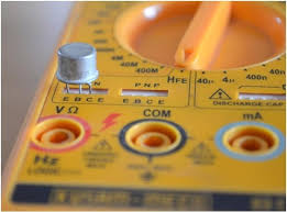
I don't know the pinout. However, if you have a multimeter with a "transistor test" socket, you can verify proper pinout yourself.
septillion:
Looks okay to me.But what is "not working"? Does it not switch on? Or not off?
What is powering it all?
So with my original circuit in the first post I made, both relays would trip with both signals, as if the voltages were being combined somehow. For instance 1 second on 1 second off for 4 trips, then both would hold on for 5 seconds on, 5 seconds off. However when observing the voltage across the relay coil, the voltage would go from about 4.6V down to about 3.4 volts when both signals were on. I want them to work independently but something is crossed somehow but I can't understand where the leakage is coming from.
When i rewired my circuit per the above, nothing works at all. Nothing trips. A 5V 3A power supply is being tripped by the transistors to supply the coils. signal is coming from arduino.
If you don't have diodes across the relay coils, the transistors have probably been destroyed. Post a link to the product page or data sheet for the exact relay module you are using.
Then, using a new transistor, with known pinout, construct a single relay circuit like the one shown on the right hand panel of post #15. Let us know how that works.
