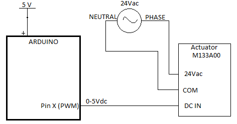
Here's a schematic that I'm sure needs to be improved upon/completed:
I think this is incomplete. Should the ground of the Arduino and ground of the 24Vac transformer be attached? Sometimes a transformer does not have a ground lead. In this case, should the ground be connected to the chassis of the transformer?
PWM - Is any filtering i.e. capacitor required on the control signal?
0-5Vdc signal - This seems to be a standard. Does the standard include how much amperage is required/drawn.
8 Actuators - The final product will be an Arduino Mega driving 8 of these actuators (hence question 3). In this case, should the control signal have it's own 5V power supply, and therefore NPN transistors, and...?
Power Supply - The spec sheet of the actuator says to size the transformer to 10A per actuator. If only one or two actuators will be operating/adjusting at a time, I think a 40A transformer should be plenty for all eight. Is that ok?
I'm confused with all the numbers: mechanical, pressure, power, 5V signal, and so on. With all those number in the documention I can't find the input impedance of the 0...5V signal, and the current used for the 24Vac. So I have to assume a few things.
1 )
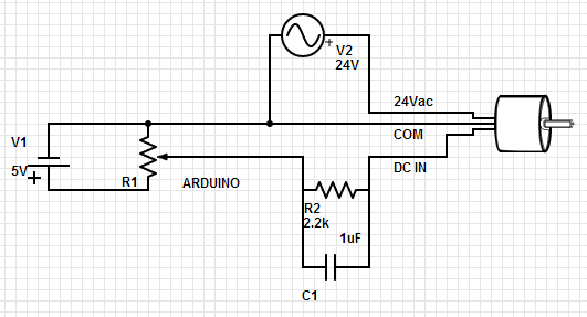
The GND of the Arduino is not the earth ground. The Arduino GND is the 0V and is the (-) of a battery.
The actuator uses 'COM' as "common ground" for the 24Vac power and the 5V steering signal. So you have to connect Arduino GND to 'COM'. Hopefully the 24Vac does not introduce electrical noise into the Arduino.
2 )
Yes. This is something I can not find in the documentation. I assume that the actuator is slow, and the Arduino PWM is about 500Hz, so a simple RC filter should be fine. Perhaps 2k2 and 1uF.
3 )
I don't know the input impedance of the actuator in 0...5V mode. I assume it is 10k, but I don't know.
4 )
8 PWM outputs of the Arduino, each with RC filter. That's all.
Most Arduino boards don't have 8 PWM outputs, but the Mega has 15.
5 )
Read it again.
They advice to use a transformer of 10VA per actuator. The 10VA can be read as 10Watt. That is the same as a transformer of 0.4A ac per actuator. With only two actuators active at a certain time, and I assume 10% for inactive actuator, I think a transformer of 1A is okay. So I advice to use a transformer of 24Vac 2A to be sure.
Do this step by step. Make an RC filter, and try to control one actuator. Let it run for a day, to see if something gets hot.
@Abe_L, Start with just one resistor and one capacitor.
Like this one: Arduino - to - Velleman K8064 DC-Controlled Dimmer - #2 by system - Interfacing - Arduino Forum
(ignore the different grounds in that schematic).
For example Arduino output pin to 2k2 resistor. After the resistor a capacitor of 1uF to ground. The signal over the capacitor is the 'analog' signal to the actuator.
@Runaway Pancae, what is the advantage of that circuit ? Do you have a reference where it was used ?
Caltoa: @Runaway Pancae, what is the advantage of that circuit ?
I wouldn't want anyone to be disappointed if the variable DC result did not climb alltheway to 5V. It could later be jiggered for more voltage and fit with a "power amp", if that will be necessary, especially in light of
Caltoa:
3 )
I don't know the input impedance of the actuator in 0...5V mode. I assume it is 10k, but I don't know.
Neither do I.
Caltoa:
Do you have a reference where it was used ?
I am quite unconvinced by the notion that this devices uses 24 VAC for power and a 0-5 V logic control signal, and uses the same "COM" ground terminal for both.
@Runaway Pancake, that circuit is to bump the signal up to 0...10V. Abe_L needs a normal 0...5V analog output.
@michinyon, I have checked the website of http://www.schneider-electric.com and I think you must be right (I should have thought of that myself :~ ). I think the actuator has 5 wires: 2 for 24Vac, 1 earth ground, 2 for low voltage control.
@Abe_L, Please give us the exact model and type. The link to some pdf file is not enough. Is a box with screws attached to the actuator for the wires ? open it, there must be more connections than just 3.
Caltoa: @Runaway Pancake, that circuit is to bump the signal up to 0...10V. Abe_L needs a normal 0...5V analog output.
@Caltoa -- Yes, Mike's was set up to go to a higher voltage - as this fellow may need, eventually. If a simple filter arrangement will suffice - fine. I still don't really know what "normal" is in this application. I didn't propose an ultimate "solution", merely a preliminary step toward an ill-defined end.