I'm working on retrofitting an existing machine to serve other purposes. The system uses a number of NPN inductive limit switches that I'd like to read into the Arduino.
The problem is that these limit switches operate on a 10-30 VDC level, and will be being used with 24VDC to match other voltages in the system. As the Arduino (currently using an UNO that was lying around, but will be upgrading to MEGA for the extra IO) only supports 5VDC, I'll need something to step it down. I'd like to shy away from custom circuitry if at all possible (otherwise I'd just use a voltage divider circuit and be done with it).
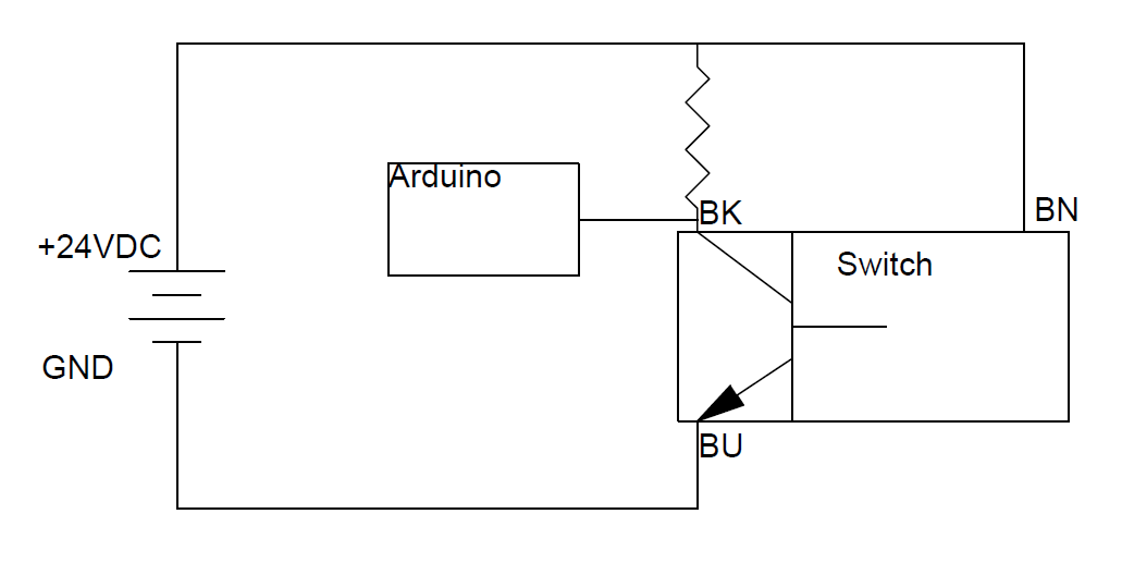
After some digging, I think I've come up with a solution, but I wanted to run it by you guys to make sure it will work (the last thing I want to do is send 24 volts into the input pin). I have attached the wiring diagram of the sensor and a basic sketch of the schematic for the system. When the switch is closed, I have no doubt that it would work (it shouldn't to much of a resistor to hit what I need it to, and there are some easily wireable options out there without the need for a custom PCB). However, when the switch is open, I'm not too sure what the arduino would see.
Is this the best way to do this or is there a better way?
Another possible solution is a small diode (e.g. 1N4148) between Arduino pin and sensor, cathode to sensor.
Enable the internal pull up on the pin, or use an external pull up if needed.
The resistor pulls the pin up to VCC, the sensor pulls the pin to ground through the diode.
Sensor voltage and/or another load on the sensor is now irrelevant.
Leo..
I think I'll go with the logic conversion card dougp suggested. I was trying to find something like that but having no luck, guess I just used the wrong search terms.
I suppose the resistor between BK and BN can not be removed.
My idea: add a resistor between BK and BU to create a voltage divider. Doesn't work well if the supply voltage changes, though.
I really like Wawa's suggestion. Simple and independent of the supply voltage of the sensor.