Do you consider these as a general use component? There are a lot of various NPNs out there, but I find it difficult to really distinguish between them. I've been told they are usually just about the same. But I got a deal on these, so plan on using them for any application where I need a NPN if these are somewhat universal.
Those are rather low gain, low power "general purpose" transistors intended for amplifier and switching applications. You should not exceed their voltage, power or current ratings. Consult the data sheet when in doubt.
If you got them cheap, they are a very good general component to have, especially as a small driver circuit. I got 500 2N3904s way back when from Tayda for two cents each. Still using them. The 2N3903 and 2N3904 are basically the same (the only real difference seems to be that the 04 has twice the gain and better bandwidth, so I don't know why you would want the 03 except that it will be as good as the 04 for most application anyway). I hope you got them that cheap too.
A little light reading:
As jremington and JoeN have pointed out, the 2n3903 is low gain . What does that mean to you ? Well, the answer to that question depends on whether or not you know how to calculate the base resistor value based on the application. So do you ?
No, I don't have the slightest clue...
I don't have any real training in electronics. Everything I know is self taught. Which makes it a little hard to comprehend considering that math is my weakest area, along with the inability to learn another language (which really makes learning to write code difficult). But I take it one step at a time. And luckily have a friend who is an electrical engineer who struggles from time to time to teach me a thing or two.
But back to the subject, is there any chance you'd draw it out in crayons for me? Exactly what I should consider when picking a transistor, that is?
And FYI, I got these for about .08 cents US a piece. So not terribly cheap, but cheap enough that I couldn't pass them up. I have used 4401s for basic amplification of audio. But that's about it.
As switches they'll be fine, and that's mostly what you'll in Arduino environment.
You'l want to run the transistor in Saturation mode, and not rely on its gain for current control.
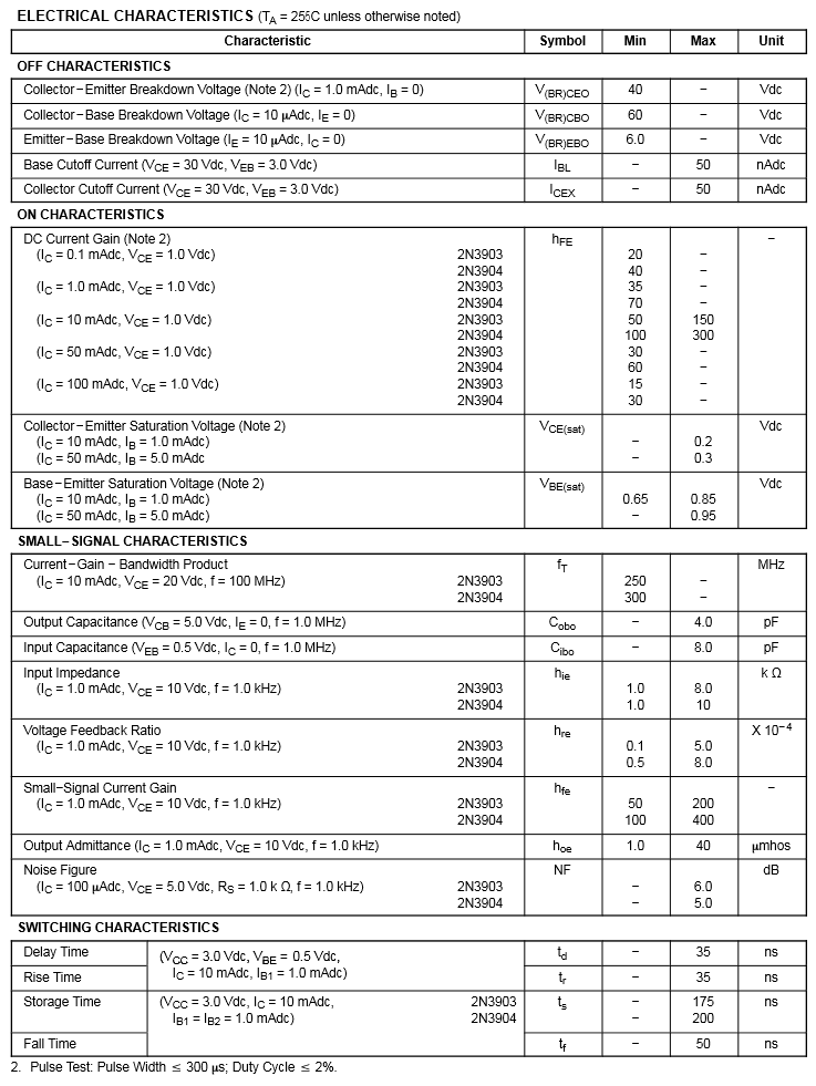
Drive 5mA into the base, it'll conduct at least 50mA thru an LED/LED string or motor for instance, with 0.3V from Collector to Emitter. The current will be limited by the motor's coil resistance, and a current limit resistor in series with the LED(s).
When you're putting in 5mA, the Base to Emitter voltage will be no more than 0.95V.
Arduino output voltage when driving 5mA will be close to 5V, so the resistor needed is:
(5V - 0.95V)/.005A = 810 ohm. An 820 is a standard value; a 750 is also a standard and should work fine also.
If I am understanding you right, the resistor is simply needed to drop the current to the npn, so that when used as a switch it only allows 5mA when turned on?
I haven't played with using resistors as switches. I just haven't gotten to that point in the learning experience yet, or skipped it. I have usually been using them for amplification of small signals, like on 8ohm speakers. So excuse my ignorance, but exactly how would you determine that your voltage in this representation would be 0.95v?
Are you using this as just an example where the desired voltage and current are a given or desired, and this is the formula for reaching it? Or is this something that should be stored in my personal memory bank (aside from the basic formula that is)?
The resistor is to limit the current flow from the Arduino pin.
You could go as low as
(5V - 0.95V)/.035A = 115 ohm; but once the transistor is saturated, there is no need - on is on, more current just equates to more heat in the base-emitter junction of the transistor, up to the limits of what the part can handle - 50mA in this case. Maybe it can do more, that data was not presented tho. The performance charts show current up to 100mA with worsening results at the higher current flow:
http://www.mccsemi.com/up_pdf/2N3904(TO-92).pdf
Once saturated, the current from collector to emitter is determined by whatever circuit is out there - say 12V to 3 Red LEDs with Vf of 2V in series thru a TBD ohm resistor, to the collector, with emitter to Gnd, and you want 20mA to go thru the LEDs:
(12V - 2V - 2V - 2V - Vce(sat) of 0.3V)/.02A (desired current) = 285 ohm
Vbe(sat) of 0.95 is from the last line of the chart under On Characteristics.
Vce(sat) is right above it.