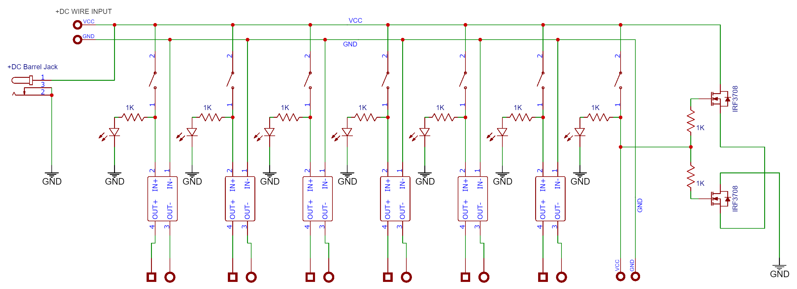
I have an power rail circuit that i will use for powering my breadboard projects with 3.3V and 5V + an direct DC channel that gives the same voltage out as in.
I have looked around for reverse polarity solutions that is bullet proof and found this schematic.
I have search alot, and i'm still some confusing. The one circuit i posted suppose to work and are not made by me. I want to use that circuit (if it works) and the mosfets i have in hand is IRFL3705, IRF3708 and IRLML2502. All N-channel Logic Level Mosfets.
If that's the case then the only way is to try it and see if it works, The worse that can happen is the release of magic smoke and a little bang if it dont work
You don't need 2 mosfets and you don't have to use the mosfet in the shcematic I showed you, That circuit works perfectly wel.
How the circuit works.
The PMOS is used as a power switch that connects or disconnects the load from the power supply. During the proper connection of the power supply, the MOSFET turns on due to the proper VGS (Gate to Source Voltage). But during the Reverse polarity situation, the Gate to Source voltage is too low to turn on the MOSFET and disconnects the load from the input power supply.
The 100R resistor is the MOSFET gate resistor connected with the Zener diode. The Zener diode protects the gate from overvoltage.
In your schematic you've drawn is wrong because the VCC can be supplied to the stepdown converters before the mosfet's .
Have you got a link to that original shcematic to see if I can get my head around how it should work ?
Hi,
Can I suggest a fuse in the positive line, and a reverse biased diode across positive and negative.
Then if you have a reverse polarity situation, the diode conducts and the fuse blows.
Yes, off course. I know that circuit. This is my backup plan. But i also want to know how i can make an bulletproof reverse voltage protect circuit with N-channel mosfets.
I will use N-channel mosfets because i do not have P-channel mosfets right now. I just need help to make the circuit i posted earlier right, regards to the reverse voltage protection with two n-channel mosfets.
Your schematic is still wrong, You won't get electrified it will just produce the magic smoke signal.
Just give up on your N-CH MOSFET obsession and buy some P-CH-MOSFET'S . Has to us your not listening what we are trying to say,
Sorry can't help you know more has you've still not provided a link, I did a quick search and found your schematic that was posted over 8-10 years ago but with no information on another forum
I've had a quick look at that post and all I can say is WHOW, You must trust others more than some other people and rely on a posted picture which was posted 10 years ago with little or no information about it and only one person say's I've built and it works,
The idea is there's one for high side and one for low side.
Your trying to use the LOW side in HIGH side you need move it to low side so that no ground (-) get's fed into the board if connected wrong. The OP could not even be bothered to reply to that thread. And I'm not sure why his using to mosfet's in series for either pointless.
Why don't you just use a signal P channel Mosfet it's doing the same job with no voltage loss like the one I posted. If you are getting voltage drop then your not fully turning the mosfet on.
I use Rapid electronics or RS components mostly for my parts unless there is already built module of E-bay
This guy explains it all in detail if you wanted to learn https://www.youtube.com/watch?v=eS4_6XQi74c