3-fan controller with OLED Display and navigation knob?

PaulRB,

According to my findings, the Arduino Uno I linked earlier will fit in the top 5.25" drive bay with room to spare. I considered your other options (and thank you for recommending them), but they were more expensive and I need to stay within budget, hence the cheaper (and bigger) Aruino Uno.

Ohm Resistance Findings

Higher resistance = lower temperature
Lower resistance = higher temperature

Regular room temperature produces the ~10K ohm resistance. Granted the cooking thermometer is not 100% precise and accurate, what is the best way to scale the Resistance values with real temperature values? i.e. is there a standard norm or scalar that is used for these type of 10K ohm sensors?

How does this sketch look for the 20 x 4 Character OLED display?:

//***************************************//
// --- WIDE.HK---//
// --- Revised Date : 02/05/2014
// --- I2C Arduino - Arduino UNO Demo ---//
// --- SSD131x PMOLED Controller      ---//
// --- SCL, SDA, GND, VCC(3.3v -5v)   ---//
//***************************************//

#include <Wire.h>          // *** I2C Mode 
#define OLED_Address 0x3c
#define OLED_Command_Mode 0x80
#define OLED_Data_Mode 0x40

void setup()
{
  Wire.begin();
}

void loop()
{
int i;
 // *** I2C initial *** //
 delay(100);
 sendCommand(0x80);
 sendCommand(0x2A);	// **** Set "RE"=1	00101010B
 sendCommand(0x71);
 sendCommand(0xC0);
 sendCommand(0x00);
 sendCommand(0x28);

 sendCommand(0x08);	// **** Set Sleep Mode On
 sendCommand(0x2A);	// **** Set "RE"=1	00101010B
 sendCommand(0x79);	// **** Set "SD"=1	01111001B

 sendCommand(0xD5);
 sendCommand(0x70);
 sendCommand(0x78);	// **** Set "SD"=0
 
 //sendCommand(0x08);
 sendCommand(0x09);	// **** Set 5-dot, 3 or 4 line(0x09), 1 or 2 line(0x08)


 sendCommand(0x06);	// **** Set Com31-->Com0  Seg0-->Seg99
 sendCommand(0x72);
  sendCommand(0xC0);
   sendCommand(0x01);
 // **** Set OLED Characterization *** //
 sendCommand(0x2A);  	// **** Set "RE"=1 
 sendCommand(0x79);  	// **** Set "SD"=1

 // **** CGROM/CGRAM Management *** //
// sendCommand(0x72);  	// **** Set ROM
// sendCommand(0x00);  	// **** Set ROM A and 8 CGRAM

sendCommand(0xDC);  	// **** Set ROM
sendCommand(0x00);  	// **** Set ROM A and 8 CGRAM

 sendCommand(0xDA); 	// **** Set Seg Pins HW Config
 sendCommand(0x10);   

 sendCommand(0x81);  	// **** Set Contrast
 sendCommand(0xD9);  	// 
  sendCommand(0x8F);  	// **** Set Contrast

 sendCommand(0xF1); 

 sendCommand(0xDB);  	// **** Set VCOM deselect level
 sendCommand(0x30);  	// **** VCC x 0.83

 sendCommand(0xDC);  	// **** Set gpio - turn EN for 15V generator on.
 sendCommand(0x03);

 sendCommand(0x78);  	// **** Exiting Set OLED Characterization
 sendCommand(0x28); 
 //sendCommand(0x2A); 
 //sendCommand(0x05); 	// **** Set Entry Mode (invert)
 sendCommand(0x06); 	// **** Set Entry Mode

 sendCommand(0x28); 	// **** Set "IS"=0 , "RE" =0 //28
 sendCommand(0x01); 
 sendCommand(0x80); 	// **** Set DDRAM Address to 0x80 (line 1 start)

 delay(100);
 sendCommand(0x0C);  	// **** Turn on Display


 // ********************************************************************//
 // **** Show Data Value *** //

send_string("\0"); send_string("1 English - Term 6  ");   //1 ??line
send_string("\0"); send_string("2 English - Term 7  ");   //2 ??line
send_string("\0"); send_string("3 English - Term 8  ");   //3 ??line
send_string("\0"); send_string("4 English - Term 9  ");   //4 ??line

/*
sendCommand(0x2C); //2 in 1 line

*/
   
 while(1);

 // **** Show Data Value *** //

}


void sendData(unsigned char data)
{
    Wire.beginTransmission(OLED_Address);  	// **** Start I2C 
    Wire.write(OLED_Data_Mode);     		// **** Set OLED Data mode
    Wire.write(data);
    Wire.endTransmission();                     // **** End I2C 
}

void sendCommand(unsigned char command)
{
    Wire.beginTransmission(OLED_Address); 	 // **** Start I2C 
    Wire.write(OLED_Command_Mode);     		 // **** Set OLED Command mode
    Wire.write(command);
    Wire.endTransmission();                 	 // **** End I2C 
      delay(10);
}

void send_string(const char *String)
{
    unsigned char i=0;
    while(String[i])
    {
        sendData(String[i]);      // *** Show String to OLED
        i++;
    }
}

Hmm... not quite as "standard" as I was hoping (I thought the display might be compatible with the standard Aduino lcd library) but as long as you have a working example to demonstrate how to code for it, that's the important thing. Most of that code seems to be for initialising the display (and should really be in the init function, not loop) and there are ways to simplify that.

Nano 3 and Pro Micro are generally cheaper than Uno. I have purchased Pro Micro for less than £2.50 and Nano 3 for around £3 from China/HK on eBay.

Will this Arduino Nano suffice if I want to control a 3rd fan and add a 4th sensor later?:

http://www.ebay.com/itm/331178319577

Yes, that shouldn't be a problem.

This table shows the differences between Uno and Nano 3:

Nano can be very cheap from China:

http://www.ebay.co.uk/itm/Arduino-Nano-V3-0-with-ATMEGA328P-Module-/291200554253?pt=UK_BOI_Electrical_Components_Supplies_ET&hash=item43cce7d50d

I just spotted this screw-terminal adaptor - could be useful

http://www.ebay.co.uk/itm/Nano-Terminal-Adapter-Board-for-the-Arduino-Nano-V3-0-AVR-ATMEGA328P-AU-Module-/281349447954?pt=UK_BOI_Electrical_Components_Supplies_ET&hash=item4181bbe112:

It has arrived :slight_smile: . So, how do I connect all this?

By doing it one thing at a time, getting a short test sketch working for each component. Only then start combining them.

So... list what you have so far. Do you have a breadboard, some resistors, caps, leds and some solid-core hookup wire? What type of Arduino?

If this is your first Arduino circuit, start with the basic flash-an-led sketch first so you know you have the Arduino IDE installed and working and you can upload a sketch.

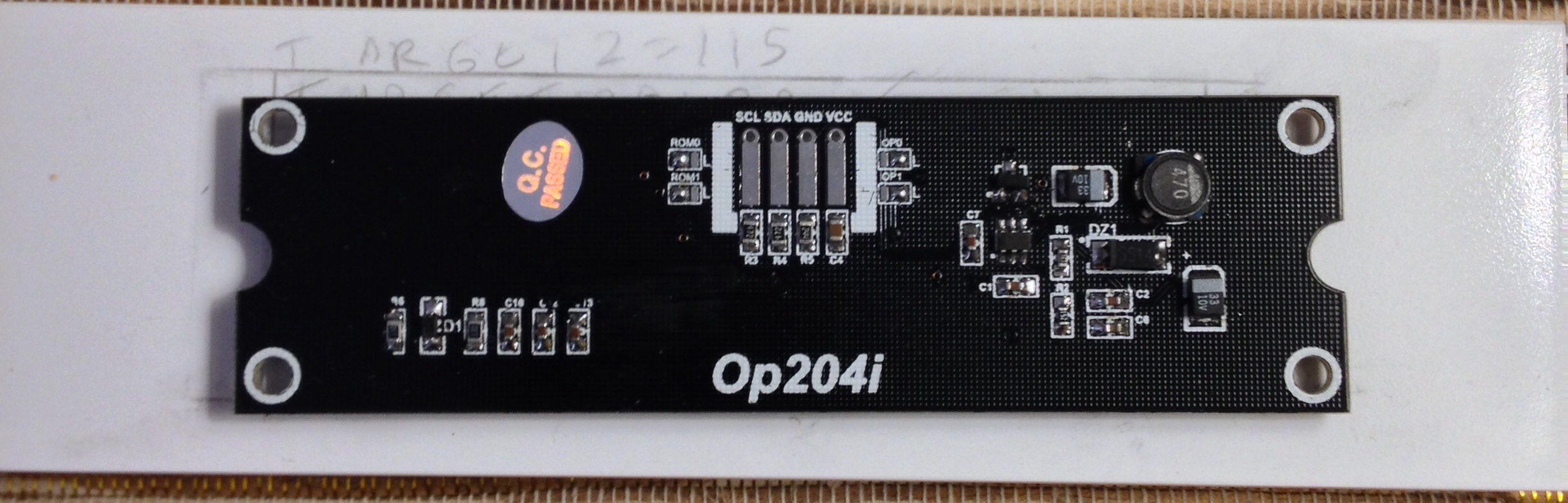
Then maybe hook up that display and run the test sketch that came with it. The picture of the connectors on the back of the display from the eBay page was blurry. Post an up-close pic. Its an i2c interface, so there should just be 4 connectors: +V, 0V, SCL and SDA. The SCL/SDA connectors must go to specific connectors on the Arduino. Which ones depends on the type of Arduino. You may also need pull-up resistors (usually 4K7) between SCA and +V and SCL and +V.

yes = have
no = do not have...yet :stuck_out_tongue:

As I'm trying to keep cost as low as possible and use what I have. Here is what I have now:

  1. solid wire 26 awg = yes
  2. Many ~57 ohm resistors and four 3.3K ohm resistors = yes
  3. Arduino Uno R3 = yes
  4. Breadboard = yes
  5. LED bulb = have old flashlights and devices that have LED, but no singular LED bulb.
  6. caps meaning capacitors? = no ( might be able to find some in some junk electronics @ home )

Regarding my temp sensors, is my understanding correct I can plug these 2-pin connectors directly into arduino pins?

Thanks PaulRB!

Have you sucessfully upload anything to the Arduino yet?

Clearly you are going to have to solder some wires to the connectors on the back of the display. Use 4 different colours, ideally red to Vcc, black to Gnd, 2 other colours to sda and scl. Then connect them to +5V, 0V, sda and scl either directly to the Arduino connectors or via your breadboard. Its usual with i2c bus to have a pair of pull-up resistors on sda and scl, but on Uno you can sometimes get away without them.

Then try uploading the sketch you were given for the display. If the sketch uploads ok and nothing happens, try connecting via the breadboard and use your 3K3 as pull-ups.

You cant connect the temp sensors direct to the Arduino because you need to form a voltage divider with a 10K resistor. Have another look at that link you posted earlier to remind yourself.

But concentrate on the display first.

This page tells you which outputs do which jobs on the uno

You will be using the Analog pins for the thermistors, pwm pins for the fans and the i2c bus is referred to as the twi bus on that page.

I got the display working on the 3.3 volt pin for the Arduino Uno R3. :slight_smile:


Regarding these temperature sensor inputs, does it matter which end I connect these 10k-ohm resistors to?

Lastly, how do you Arduino gurus recommend I proceed with the code to make it all work?

Thanks for all of your expert guidance and I look forward to learning from you all and sharing the results!