hi guys i need your help i got a 3phate current transformer ZMCt308 for 400amps readings
this CT give 25-100mah output so i decide to add a 18ohms burden resistor to get a 5v output , i been testing my instalation to read the current output with EmonLib
but this CT have 4 cables a neutral and 3 outputs
so im having trouble reading the value from it , and my guess is my conection , what do you think is the correct way to check this,
also do you know if is possible to read the same CT with two devices?
thanks knut_ny i notice that the output was AC , to be honest i am a little bit green with electronics , do you have a ny diagram where i can see where to add the bridge rectirier?
WarLion:
thanks knut_ny i notice that the output was AC , to be honest i am a little bit green with electronics , do you have a ny diagram where i can see where to add the bridge rectirier?
What exactly are you trying to do? You can't just add the three phase current values together to get the power being used by the connected device.
hi paul thaks what i need is to display in a lcd the current for each line , im use to the sct 013 000 , but this current transformer give 100mah output and 1 commun for the 3 trasformers , there is where im lost
WarLion:
hi paul thaks what i need is to display in a lcd the current for each line , im use to the sct 013 000 , but this current transformer give 100mah output and 1 commun for the 3 trasformers , there is where im lost
Then you have a real three-phase transformer, which is actually three transformers connected just as you described. This "transformer" will allow you to determine the actual phasing between the three power leads on your primary power. I don't think it will allow you to do what you want. You need three current transformer with completely isolated secondary windings.
i want to get tha same data to display nad after that mqtt , but im unable to read the data ,
this is the transformer
Think about measuring the AC voltage between one lead and the common wire. Then find three transformers that can use that voltage as the primary voltage and give a similar voltage on the transformer secondary winding. Then you have a voltage source the is completely isolated from the other source. With this you can rectify and filter and get a DC voltage you can use with your Arduino.
Its vitally important with a CT that the burden resistor(s) can never become disconnected - immediate
very high voltages could ensue. Lethal voltages are entirely possible, perhaps flashover and fire.
Thus using a breadboard for connecting burden resistors is super dangerous to my mind - the burden resistors
should be securely wired to the CT leads in a rock-solid manner, crimped, soldered, screw terminals, or any
other method that cannot work loose by accident. Only then can you assume the secondary is going
to be safely low-voltage.
A step-down current transformer without a burden resistor becomes a step-up voltage transformer capable
of generating many kilovolts in theory - certainly capable of burning itself out, then shorting internally
and overheating.
I would always recommend getting CTs with built-in burden resistors as these are much safer to work with.
WarLion:
...but this CT have 4 cables a neutral and 3 outputs...
Seems that you only need one mid-voltage circuit (two equal resistors and one buffer cap).
With the common of the transformers connected to that point.
And three burden resistors between each 'hot' winding to that common point.
Then connect those three 'hot' points to three analogue inputs.
Leo..
leo can you write a diagram , to complete get your information im really sorry about that leo but my brain is not working after 2 days fighting this one
Don't think I can explain it more clearly, and no time to draw a diagram.
The Arduino can only measure positive voltages, so the common wire of that transformer needs to be lifted to mid-voltage (~2.5volt) to prevent the AC signal from going negative.
That's why you connect that common wire to a 10k:10k voltage divider (with or without the 10uF smoothing cap).
The three other/hot wires from the transformer connect to three analogue inputs.
If you also have to add burden resistors across each of the three transformer windings depends on if those burden resistors are already buildin or not.
Leo..
i want to get tha same data to display nad after that mqtt , but im unable to read the data ,
this is the transformer
If the current transformers are already in circuit, then the burden resistor are already present, so you do not need to add them.
If you do then the readings of the other monitor will be affected.
Unless you are trying to make a replacement unit?
Can you tell us your electronics, programming, arduino, hardware experience?
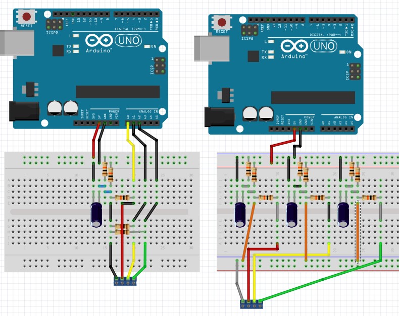
Can you please post a copy of your circuit, in CAD or a picture of a hand drawn circuit in jpg, png?
A proper schematic, not a fritzy, labeling the pins and terminals you are wired to.