
My thesis project is to make a water bottle mount that measure the mL inside of a 32oz. For that, is it possible to connect 3 wire load cell to HX711? Usually a single load cells (the rectangular one) have 4 wires: White, black, red, green.
Yes, but 4-wire cell would be better.
Make a search on this forum, you find instructions.
This for example:
1 Like
Yes it is. However the loadcell you show is probably not sensitive enough.
1 liter of water weighs 1000g so for maximum resolution you would a loadcell with a maximum in that range. The one you show, I believe has a max value of 50000g and will not give you the resolution you need.
You need to find a different loadcell
1 Like
Hello! So according to this forum (though i may not understand some of it, im still new at electronics) I should connect the E - wire (black) and E + (red) together with a 1k resistor? and it should work?
Should a single load cell like this work?

I purposely chose the bathroom load cell specifically for my 3D mount and it fits perfectly, though i cant seem to make it work
1 Like
That would be much better and more accurate.
2 Likes
There aren't many good datasheets for those three-wire half-bridge load cells, Sparkfun Load Sensor - 50kg (Generic) - SEN-10245 - SparkFun Electronics has:

The trick is that a half-bridge (half of a Wheatstone Bridge) like that is just a voltage divider that changes it's middle voltage 0.1% when you load it to the full value, (+0.005V on the HX711's 5V excitation voltage) You need another half of the wheatstone bridge to provide a reference value for the HX711 to measure that 0.1%, of change against. or the other half of the bridge can use another gauge as a dummy, or a potentiometer you can adjust to match the 2.500V.
For the milliliter sensitivity range you are talking about, 1ml = 0.001kg and 0.001kg/50kg=1e-6 times the full-scale sensitivity of the gauge gives a signal of 0.005V=100nV/ml, which is pretty tiny. But the HX711's 24 bit ADC range and x128 amplifier advertises 2.5V/128/2^23=2.3nV resolution, so there's a chance.
Good luck!
1 Like
Thank you for a detailed explanation of the bathroom (half-bridge) load cells, though i may not understand completely (since im relatively new at electronics) i do understand that i should have another half bridge connection, i.e. another load cell or a potentiometer in order to work? correct me if im wrong please
*edit: is it possible to make a wiring with resistors? just like in this previous forum:
Yes. With one half-bridge, you only have one input to the HX711 inputs. For example you have A+, and you need a reasonable reference signal to put into A-.

1 Like
Yes, but you should make sure the selected resistors are balanced enough to match your cell. Some folks use 10% tolerance resistors and have troubles when the difference between the load cell's voltage and the resistor's voltage divider voltage is >20mV. Which, with the x128 amplification, pegs the HX711 scale at +/-2^23=8388608 You should use the more expensive 1% resistors, or a pot, or a couple cheaper resistors and a pot to make the reference voltage. All will work.
1 Like
What accuracy do you want? +/-1g?
You won't get it with a 50kg loadcell
1 Like
1. This (your post #5) is a cantilever type load cell and mount it on the bench as Fig-1:
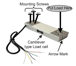
Figure-1:
2. Connect it with HX711 Board as follows (Fig-2):

Figure-2:
3. Create and upload a simple sketch into Arduino UNO to check the functionality of the Load Cell. After that you may use Library or 2-point Calibration to detect/measure actual load on the Load Cell.
4. Fig-3 is a typical application of half-bridge 3-Wire load cell:


Figure-3:
1 Like
A 5kg load cell would be a bit simpler to wire up, and instead of a 100nV/ml signal, it would have a 1000nV/ml (1 uV/ml) signal for the HX711's and likely be 10x more accurate.
Another issue on using the bathroom half-bridge cell is that you have to make sure the center arm can bend like a sigmoid curve with load -- support it around the rim, not anywhere in the middle and concentrate the force on the nib in the center on the wire side.

If the cell isn't supported properly, the center bar won't bend well, and the strain gauges won't stretch predictably.
So have you decided on the 5kg load cell of post #5 ?
1 Like
Another issue is that you have a HX711 board for 5volt processors.
Only Sparkfun sells HX711 boards that are suitable for 3.3volt processors, like the ESP32.
Leo..
well i supposed this will do the trick, since it is hassle free from any wiring and more accurate than this bathroom load cell, thank you everyone for replying! much appreciated.
Yes it will but as @Wawa pointed out, the HX711 has 5V signals and the ESP can only connect to 3.3V signals.
1 Like
The simple solution is a 2-resistor voltage divider, to drop the 5volt-logic data line to 3.3volt.
- 1k resistor between HX711 data out pin and ESP data input.
- 2k2 resistor between ESP data input and ESP ground.
Don't use one on the clock line.
A better solution is to use a Sparkfun HX711 board, which has a 5volt supply pin for the load cell and a 3.3volt supply pin for 3.3volt logic. Or you could modify your board if you can solder. Schematics are on the Sparkfun site.
Leo..
Ah yes, didnt noticed your comment. Thank you for that. I should do the 2 resistor divider first to test it out (and for experience too).
As per sir @jim-p's suggestion, i should buy the straight bar load cell rather than this hassle wirings too
I was trying this load cell to make it into a full bridge (from the first comment's suggestion)

it works (i think, because whenever i put a load into the cell, the reading changes) but not really accurate as it seems, and you said that this type of HX711 has 5V signals, but ESP only connects 3.3v, thank you for that.
On those cells you really have to support them around their outer rim and make sure the inner 'E" is not supported. In the photo, if you think of the shape as a "E3" with the "E" kind of inside of the "3". The E part must not rest on anything so the bar in the center bends freely into a sort of an s-shaped "____/ ‾ ‾ ‾" bend when you press on the nubbin. If it has any support, you'll get terrible repeatability.