I have two, three-wire load sensors (https://cdn.sparkfun.com//assets/parts/4/5/9/5/10245-01.jpg) hooked up in a half wheatstone bridge (I think), with two 1K resistors. Using a multimeter, I am reading small voltage changes when applying pressure to either strain gauge, when measured on between the pins A+ and A- on the HX711 ADC amp, however my Arduino serial output shows all 0's when using a variety of code examples (for example, this one: Weight_Sensor_Module_V1-DFRobot).
My concern is that my circuit is not setup correctly as I am fairly novice, however everything I have researched about wheatstone bridges, and half wheatstone bridges seems fairly straightforward, and seems to match my circuit. Any guidance/advice on the attached breadboard circuit diagram would be extremely helpful.
I'll have to lookup the type of resistors, they came with the arduino starter kit I got. Regarding the strain gauges, I'm not sure how to wire it up using all three. From what I could tell the resistance between red/white was 1K, red/black was 1K, and black/white wss 2K.
Any idea how/where to incorporate all three wires? And does the bridge circuit and inputs to the hx711 look right? Sorry, just been struggling with this seemingly trivial circuit for waaayyy too long.
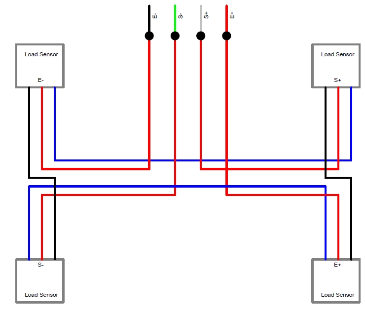
One white and one black (from different strain gauges) should be E+ and then the remaining white and black to E-; your two red wires should go to A+ and A-. There's no need for those resistors.
Chagrin:
One white and one black (from different strain gauges) should be E+ and then the remaining white and black to E-; your two red wires should go to A+ and A-. There's no need for those resistors.
Exactly right, you must connect it this way - it forms the proper bridge to give compensation and sensitivity (but you can exchange the E+and E- with the A+ and A- for exactly the same effect). And there is a clever way to connect four sensors as well.
Well, it might almost be, except that for some bizarre reason, you seem to have the E+ pin tied to Vcc which would seem to interfere with the regulator on that board.
