315mhz SYN470R receiver with Arduino

I'd like to replace the micro controller in my 16 ch 315mhz relay board with an Arduino. The relay board's wireless receiver is a syn470r and I have a 2nd identical receiver to use for experimenting with the Arduino. I briefly tried to use the RadioHead library's ASK example but I don't receive any data from the receiver. I have the VCC, Gnd and Data lines connected to Arduino 5V, Gnd and io 11. Here's my sketch, any help would be appreciated.

#include <RH_ASK.h>
#include <SPI.h> // Not actualy used but needed to compile

//RH_ASK driver;
RH_ASK driver(2000, 11, 12, 10, false);

void setup()
{
    Serial.begin(115200);	// Debugging only
    while(!Serial);
    if (!driver.init()){
      Serial.println("init failed");
    } else {
      Serial.println("init complete");
    }

}

void loop(){
  uint8_t buf[RH_ASK_MAX_MESSAGE_LEN];
  uint8_t buflen = sizeof(buf);

  if (driver.recv(buf, &buflen)){ // Non-blocking
    int i;
	  driver.printBuffer("Got:", buf, buflen); // Message with a good checksum received, dump it.
  }
}

If I press buttons on the 315mhz remote, the only serial output I see is the "init complete" message.

The remote is probably not an Arduino board with a transmitter. A cheap remote probably uses the 2272/2262 protocol. That protocol is completely different from the protocol that RadioHead ASK uses.
For the 2272/2262 protocol you need the rcswith or the fuzzillogic library. The rcswitch library has an advanced example that can tell the timing of the signal.

The RadioHead ASK can only receive data is also transmitted with the RadioHead ASK (or VirtualWire) library.

A simple way to test for a remote which uses the PT2262 protocol is try and turn on 2 or more of your relays at the same time.
The PT2262 encoder normally transmits a 4 bit nibble which allows 1 of 16 devices to be turned on or off.
If you can turn on 2 or more at once then its not PT2262 and rcswitch wont work.

mauried:
A simple way to test for a remote which uses the PT2262 protocol is try and turn on 2 or more of your relays at the same time.
The PT2262 encoder normally transmits a 4 bit nibble which allows 1 of 16 devices to be turned on or off.
If you can turn on 2 or more at once then its not PT2262 and rcswitch wont work.

When we press 2 buttons at once, it's as if it sums the button values (resistors) and a 3rd relay switches.

Koepel:
The remote is probably not an Arduino board with a transmitter. A cheap remote probably uses the 2272/2262 protocol. That protocol is completely different from the protocol that RadioHead ASK uses.
For the 2272/2262 protocol you need the rcswith or the fuzzillogic library. The rcswitch library has an advanced example that can tell the timing of the signal.

The RadioHead ASK can only receive data is also transmitted with the RadioHead ASK (or VirtualWire) library.

Thanks for the pointers, I will look into these libraries and protocols.

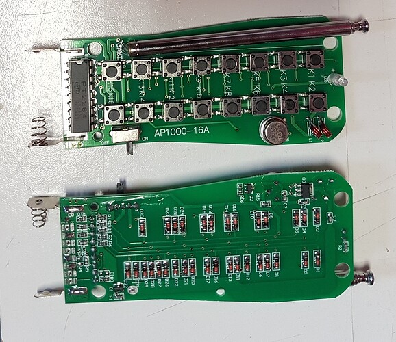
So I got the RCSwitch library to work after I figured out that the Leo uses a diff IO for Interrupt 0. After opening up my remotes and reading PDFs, I found out my transmitters use a PT2264 chip PDF with a APRXB12 receiver board (SYN470R chip) PDF

Using the RCSwitch library, ReceiveDemo_Simple outputs the follow for button 1 on transmitter 1 & 2:

Received 5594371 / 24bit Protocol: 1
Received 6053123 / 24bit Protocol: 1

Receive_Demo_Advanced output for button 1 on transmitter 1 & 2:

Decimal: 5594371 (24Bit) Binary: 010101010101110100000011 Tri-State: FFFFFF1F0001 PulseLength: 442 microseconds Protocol: 1
Raw data: 13700,464,1336,1296,524,364,1396,1260,528,356,1400,1268,532,352,1392,1272,516,368,1404,1264,516,372,1396,1272,512,1264,512,1272,520,372,1384,1276,520,368,1396,376,1388,384,1388,380,1392,380,1388,384,1384,1276,516,1268,512,


Decimal: 6053123 (24Bit) Binary: 010111000101110100000011 Tri-State: FF10FF1F0001 PulseLength: 452 microseconds Protocol: 1
Raw data: 14020,464,1368,1308,540,360,1432,1276,540,1264,548,1260,548,348,1440,376,1440,364,1432,1276,532,368,1440,1264,544,1264,540,1264,548,360,1440,1268,556,348,1436,376,1428,372,1432,372,1432,376,1428,384,1416,1288,528,1276,532,

Two more pics

Well done :smiley:

It is the common protocol.
I think that the PT2264 and PT2262 are almost the same.
Do you understand the protocol ? The chip has tri-state pins, they can be high, low, or in the middle. The burst of data is transmitted a number of times, to be sure that the receiver got it.

The rcswitch uses a number, so you only have to look for a specific number.

When nothing is transmitted, the auto-gain of the receiver will amplify the signal until there will be a lot of noise. That noise will generate interrupts for the rcswitch library. It can be thousands of interrupts per second. That is normal, but it stresses the Arduino. You can not do a lot of other long interrupts or disable interrupts for too long.

The advanced example says "442 microseconds" and "452 microseconds". Can you try to find a average value ? or perhaps that was only needed for the transmitter.

Now you have the rcswitch library working, you know the timing, the protocol and the numbers for the buttons. That means you can receive data and also send data (if you buy a transmitter).

Always use the receiver with a antenna. Without antenna they don't work very well.

With a 10 dollar USB stick, you can do SDR and receive the signal.
You can also make a attenuator with two resistors to lower the output of the receiver for the line-in of the computer and use Audacity to record the data.
Not that it is needed, now that you have it working, but just for fun.