How to use RF module?

Hello,

I've had this 315 MHz RF transmitter and receiver (purchased from: eBay Page) for a while now and am struggling with how to use it. I want to be able to determine which button I push on the standalone remote, using the receiver module.

The receiver chip is marked SC2272-M4 and the transmitter in the remote control is SC2262. I found a datasheet that states that these do work together. The pins seem to all be in the same configuration (top row all soldered, bottom row all open). The transmitter board is marked XY-T4 and the receiver module is marked XY-DJM-5V.

I have looked at various RF module pages but I am still having trouble with getting this to work. Most RF module tutorials I have seen seem to use VirtualWire (which I do not think I can use because my transmitter is not placed on another Arduino) or RCSwitch (does not seem to support my RF chip according to documentation).

So far, I have tried reading from analog and digital but without any luck. Per the eBay description and one tutorial (although they were using a 2 channel system), I read the VT pin to determine if there was any input before looking at the channels. With analog, I get a pattern of values that does not seem to change when I push the remote. However, it is going quickly, so it is possible I just did not see any change. Is there a way to slow the Serial Monitor down? With digital, I keep getting a value of 1 printed to the Serial Monitor.

Am I doing any of this right? Should I be doing something else instead?

Attached are photos of the setup and module and remote.
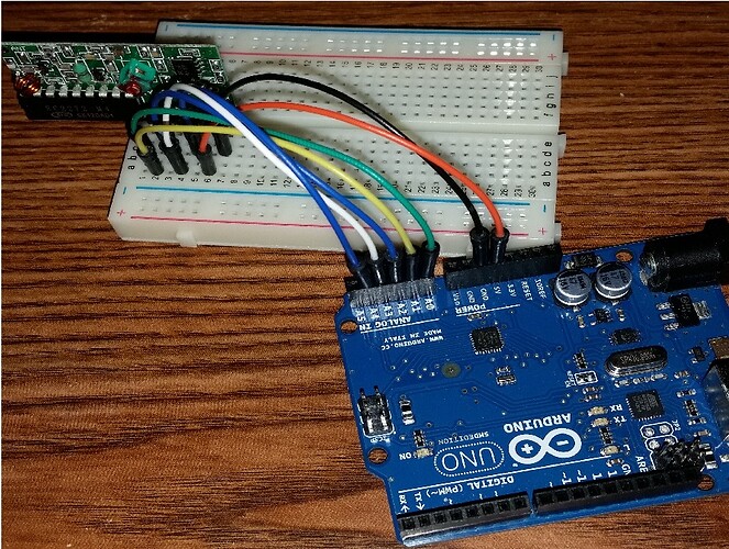
It looks very similar to one I have used. If it is the same, the output pins simply change state when the button is pressed and revert when button released.

Your program simply needs to monitor the outputs and capture the change of state.

Only one output works at a time so you will need to use the program to latch the output if required.

Weedpharma

Well, tinypic.com is something to avoid from now on. I can't see the photo, but only a lot of nasty ads.

The 2272 / 2262 is the most common protocol.
The RCSwitch supports it, start with the advanced example, it will detect the protocol and the timing.
I prefer the fuzzillogic myself. The code is cleaner and faster. The example for the RemoteSwitch will detect it.

https://bitbucket.org/fuzzillogic/433mhzforarduino/

Links to photos of my setup (photos too large to attach):

You should reduce the size of your photos anyway, then you can attach them. They should be less than 1000 pixels wide.

As far as Arduino is concerned, that those work by radio is totally irrelevant: it's just a push switch plugged into an Arduino pin. Just look at the pins as if you were reading a button.

The M4 version is a momentary switch; there are also T4 for toggle and L4 for latching. Have a look here at adafruit where they say this:

There's no programming, configuring or addressing - simply power the receiver with 5-10VDC and press the buttons on our matching RF keyfob remote. When the A button is pressed, it activates the first pin, when the B button is pressed, it activates the second one, and so forth for all four buttons.

Watch the video....

The code can hardly be simpler:

// receiver pins 0-3 connected to arduino 3-6
// receiver pin vt to an led- simple indicator

void setup()
{
  Serial.begin(9600);
  Serial.println("starting");
}

void loop()
{
  if (digitalRead(3)) Serial.println("blah");
    if (digitalRead(4)) Serial.println("qwerty");
      if (digitalRead(5)) Serial.println("yaddayadda");
        if (digitalRead(6)) Serial.println("fishpaste");
}

If you need to see that a button became pressed (ie only print one line no matter how long it's pressed) as opposed to is pressed (print as long as it's pressed) you'll need to monitor the button's state just like you would do here.

The radio aspect of this a very bright red herring: it's just 4 buttons that happen not to use wires.

Thank you for the advice!

weedpharma:
It looks very similar to one I have used. If it is the same, the output pins simply change state when the button is pressed and revert when button released.

Your program simply needs to monitor the outputs and capture the change of state.

Only one output works at a time so you will need to use the program to latch the output if required.

Weedpharma

Was yours also 4 channels? Were you using digital or analog pins? Using digital pins, all pins constantly read 1 whether or not I press a button. I made a histogram of the output pins' analog outputs and values ranged from 933 to 1023. An overwhelming number were 1023 so I assume this is the state where it is not receiving a signal. Which suggests that the other values that keep popping up could be noise. Not sure how I can reduce this further beyond moving to an isolated corner of the house.

Pushing the buttons does not seem to change the histogram.

Peter_n:
Well, tinypic.com is something to avoid from now on. I can't see the photo, but only a lot of nasty ads.

The 2272 / 2262 is the most common protocol.
The RCSwitch supports it, start with the advanced example, it will detect the protocol and the timing.
I prefer the fuzzillogic myself. The code is cleaner and faster. The example for the RemoteSwitch will detect it.

GitHub - sui77/rc-switch: Arduino lib to operate 433/315Mhz devices like power outlet sockets.
Bitbucket

Very sorry about the images...I neglected to click on them afterwards to see how they looked. I have edited my original post and attached the resized photos. I thought they would look terrible but they seem to be okay.

I tried the fuzzilogic examples briefly but did not get anything on the Serial Monitor when I pushed buttons. I haven't had a chance to take a look at the library but since it is designed for 433 MHz, do I need to tweak it for my 315 MHz device?

I will have to try it some more along with RCSwitch tomorrow since it's getting pretty late here. Will get back to you tomorrow once I've had a chance to try them out.

JimboZA:
As far as Arduino is concerned, that those work by radio is totally irrelevant: it's just a push switch plugged into an Arduino pin. Just look at the pins as if you were reading a button.

The M4 version is a momentary switch; there are also T4 for toggle and L4 for latching. Have a look here at adafruit where they say this:

Watch the video....

Yeah, I am treating it like a button but the digitalRead of any of the pins keeps reading 1, regardless of whether I push any buttons on the transmitter. Possibly defective module? Also noticing from the video that there is an antenna attached on the receiver whereas mine does not have one. Curious as to why it's reading 1 instead of 0 if it's not receiving anything due to not having an antenna.

Yeah I'd stick a wire on that empty antenna hole there.....

phpbyte:
Curious as to why it's reading 1 instead of 0 if it's not receiving anything due to not having an antenna.

Might be different electronics on the board itself (as opposed to the main chip) that takes the pins high, for an "active low" configuration.

Thanks, now I can see the photos :slight_smile:
Those modules have chips for the protocol on the board. You don't need VirtualWire or RCSwitch or fuzzillogic.
Just read the pins as JimboZA wrote.

The transmitter is transmitting that 2272 / 2262 code, and the receiver decodes it on the module.

When you have a common receiver, without the decoder chip, you can use RCSwitch or fuzzillogic to read the signal from the key fob. Those libraries can also generate that signal to be used with a common transmitter without encoder. So those libraries can emulate both the transmitter and receiver 2272 / 2262 chips.

VirtualWire has its own protocol. It is not compatible with the 2272 / 2262 code. It can be used with common transmitters and receivers without the encoder or decoder chips. Both the transmitter and receiver should be an Arduino with the VirtualWire library. The VirtualWire protocol is also a lot better than the 2272 / 2262 protocol. Because of that it has a longer range.

Mine was very similar, in fact looks identical. ( probably same but in different case).

Look at the pins, you have D0, D1 etc, connect these to the digital inputs. I assume you will use 5v so as not to damage the Arduino. You may need to tie to 5v or ground.

Look for a level change when the button is pressed. It is a digital signal. It will only be active while the button is pressed. Only one will be active at a time.

Weedpharma

This board can have the channel changed by soldering links in the back. On the edge with the pins, you will see a row of pins with rails either side. Be soldering the pins to either rail, you change the channel.

Check this is the same on your Tx and Rx.

The antenna is only needed if you want range. For testing it should be ok for a few metres or more.

Weedpharma

Happy New Year! Been really busy with work and didn't have a chance to play around more with the module.

JimboZA:
Yeah I'd stick a wire on that empty antenna hole there.....

I didn't think this was too big of a problem since the two Youtube videos I saw did not use an antenna and still worked fine. I tried it at distances of about 2 inches to a foot or two away so should be fine...

JimboZA:
Might be different electronics on the board itself (as opposed to the main chip) that takes the pins high, for an "active low" configuration.

True, forgot it could be configured the other way around. I'm just too used to 0 for off and 1 for on, I guess.

Peter_n:
Thanks, now I can see the photos :slight_smile:
Those modules have chips for the protocol on the board. You don't need VirtualWire or RCSwitch or fuzzillogic.
Just read the pins as JimboZA wrote.

The transmitter is transmitting that 2272 / 2262 code, and the receiver decodes it on the module.

When you have a common receiver, without the decoder chip, you can use RCSwitch or fuzzillogic to read the signal from the key fob. Those libraries can also generate that signal to be used with a common transmitter without encoder. So those libraries can emulate both the transmitter and receiver 2272 / 2262 chips.

VirtualWire has its own protocol. It is not compatible with the 2272 / 2262 code. It can be used with common transmitters and receivers without the encoder or decoder chips. Both the transmitter and receiver should be an Arduino with the VirtualWire library. The VirtualWire protocol is also a lot better than the 2272 / 2262 protocol. Because of that it has a longer range.

Ah okay, that makes sense. Thank you! I used Jimbo's example code in case my code was flawed and ended up continuously getting blah, qwerty, yaddayadda, and fishpaste printed out, lol. So still not sure what is going on.

weedpharma:
Mine was very similar, in fact looks identical. ( probably same but in different case).

Look at the pins, you have D0, D1 etc, connect these to the digital inputs. I assume you will use 5v so as not to damage the Arduino. You may need to tie to 5v or ground.

Look for a level change when the button is pressed. It is a digital signal. It will only be active while the button is pressed. Only one will be active at a time.

Weedpharma

I also tried this before: 5V input and D0-D4 and VT plugged into digital pins (VT-2, D0-4, D1-7, D2-8, D3-12 on Arduino Uno). However, it keeps spitting out only 1s regardless of whether a button is pushed or held down.

Is it okay that I used only the non-PWM digital pins?

phpbyte:
I used Jimbo's example code in case my code was flawed and ended up continuously getting blah, qwerty, yaddayadda, and fishpaste printed out, lol. So still not sure what is going on.

When you say "continuously"... you mean while the button is pressed or after you let go? With the M version of the chip (M= momentary) it shouldn't stay pressed once you release.

A quick button push for a human is an eternity in Arduino time. With simple code like that, it will zoom through loop at 150000 times per second according to some testing I did recently. So you'll get the text displayed a lot of times during what to you is a momentary press.

If you want it to display only once per press, have a look at the ButtonStateChange example, so set a flag when it sees that the button became pressed so ignores that it's held down.

JimboZA:
When you say "continuously"... you mean while the button is pressed or after you let go? With the M version of the chip (M= momentary) it shouldn't stay pressed once you release.)

A quick button push for a human is an eternity in Arduino time. With simple code like that, it will zoom through loop at 150000 times per second according to some testing I did recently. So you'll get the text displayed a lot of times during what to you is a momentary press.

If you want it to display only once per press, have a look at the ButtonStateChange example, so set a flag when it sees that the button became pressed so ignores that it's held down.

Continuously as in it kept looping the output of strings to the Serial Monitor regardless of whether I pushed a button or not.

Right, I know the Arduino operates a lot faster than my thumb (from experience from when I worked on the button tutorial) so I thought I would at least glimpse an output change (e.g. 0s instead of 1s). I went ahead and added an if statement to only print the signal state to the Serial Monitor if the VT digital signal != 1. Nothing shows up after my initialization string now, regardless of a button push.

So it sounds like the pins are high regardless?

Take the Arduino out of the loop then, just to help diagnose, if you didn't already.

Put 5V and ground onto the receiver, and then just read the voltage across each pin and ground.

Remove the module from the Arduino and use it stand alone.

Connect 5v and gnd. Try it now to see if it is a problem with connecting to the Arduino.

Read the output with a meter.

Weedpharma

Yes, they are high (or low, depending on the configuration) regardless.

It seems like both of you are asking me to do the same thing? Please correct me if I am wrong.

Just to make sure I don't accidentally short something by misunderstanding:

  1. Remove receiver from Arduino except for 5V and ground
  2. Using a voltmeter, red lead on each pin (VT, D0, D1, D2, and D3; one at a time, of course) and black lead on ground?

Correct.

The D0 etc pins should change state when the corresponding button is pressed.

Have you checked the voltage of the Tx battery to see if it is not flat?

Weedpharma