Hi everyone,
I am new in the world of arduino programing and electronics and would highly appreciate your help.
I have encountered a strange behavior with arduino nano.
In a project it receives two analog reference signals from 0 to 5V 10mA (from Multy-E4-MU measuring device) to pins A1 and A2.
The issue is, on the pin A2 voltage drops to 1,2V and remains stable regardless of the reference voltage rise.
This behavior was repetitive it has occurred previoulsy and was gone but, yet it has happened again.
When I remove that signal and give external 5V from other board it detects it and works as supposed to.
P.S. I was thinking that it drains a current from that pin to cover inadequate power supply of the board (I have had also that kind of issue :)). After checking the supply it turned to be adequate, other boards are functioning good with the same supply.
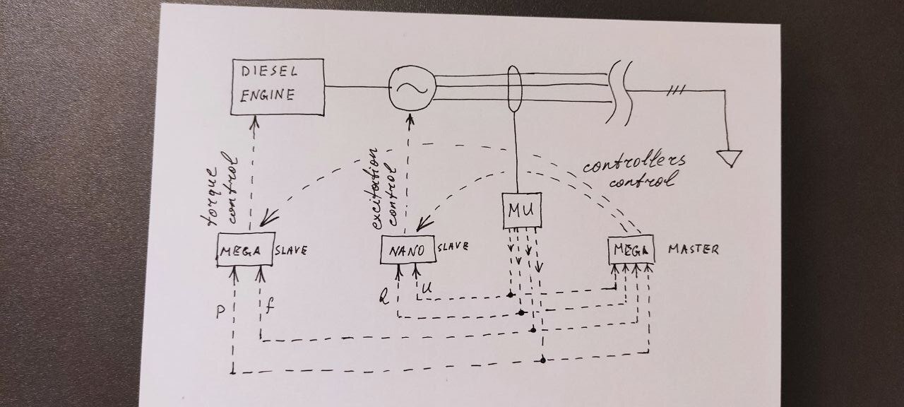
Unfortunately there is no code, it is based on simulink model (see the picture) which I am unable to upload to other board to replace this one because of some issues, so, I have to work out this problem by hardware.
I would be very grateful if someone could help me with this phenomenon.
Thank you in advance.

That does not sound correct, the Analog inputs are very high only requiring at most micro amps. An electronic schematic would help.


Maybe its me, but I don't understand why you have two boards with their analog pins connected to each other? I don't think that the analog pins can read PWM directly and will probably need some additional DA circuitry to convert the PWM to an analog signal for the analog input. But maybe I mis-understand the intention here?
actually they are not connected to each other, those are input pins receiving the same signal from the same source.
the nano and left mega are slaves -controllers for stator voltage and frequency of the generator and top mega is the master controlling them and the rest of the cycle, e.g. on, off etc..
reference voltage is not PWM it is analog 0-5V 10mA signal.
and the question is why that particular nano drains the signal current?
i have a second generators controll receiving the same signal and when i am disconnecting the nanos pin voltage builds up and everithing works well, but as soon as connect that signal to the nano voltage drops.
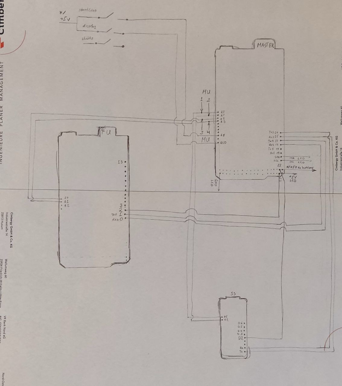
in the picture you can see how the connections are made.
but yes it is pretty confusing, i should have provided more details. sorry for that.
You misunderstand the word "connected" and "actually."
I did not understand, can you expand your thoughts please?
What do you not understand? I was very clear while referring to your quote.
in which the misunderstanding of "connected and actually" is?
Maybe you can spot the misunderstanding...
-
You posted a drawing with four pins oddly, but clearly, connected.
-
This fact was pointed out to you.
-
You denied the pins were connected.
can you please read more carefully my response? (i did not deny it)
i am drafting a simplified connection scheme so it will be more clear for everyone.
Okay.
Need pin numbers.
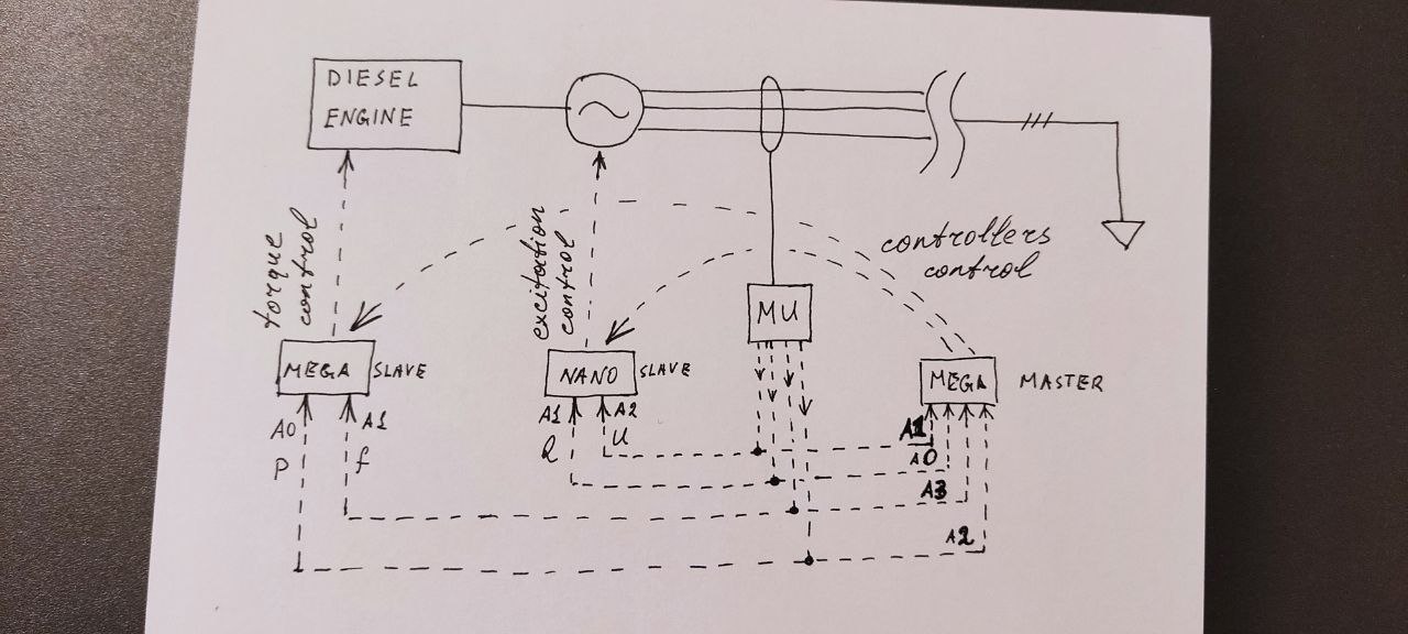
mega master A2,A3 and mega slave A0,A1 respectively,
mega master A0,A1 and nano slave A1,A2 respectively,
only A2 pin of nano is problematic. rest are good.
Pin numbers on the drawing... who wants to scroll around matching names and wires?
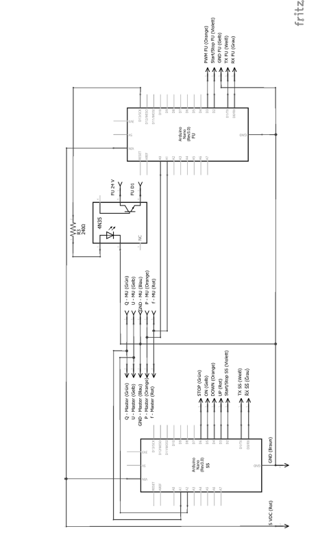
Ok, to clarify I am looking at the hand drawn diagram. The digital ones are almost unreadable but I did try ![]()
I missed the fact that your hand diagram has the numbers 1&2 and 3&4 against the analog pins on the Mega along with the label 'MU'. Given your comment (and the additional drawing just added in #17 which crossed with my post) I now assume that the 'MU' marking must refer to a pair of signals coming in your Multy-E4-MU, each 'MU' referring to a separate channel? However, in that case you have two Arduinos in parallel (Mega-Master + Mega-Left) and (Mega-Master + Nano) reading the same signal?
It might be possible to swap out the original Nano but you would need to download the binary code from the original one. To do this would require a USBASP programmer using the avrdude program (or optionally with the avrdudess GUI which makes it a bit easier), or another Arduino set up as an ISP programmer. The saved code would then need to e uploaded to the substitute Nano in the same way. That might prove whether there is a faulty pin on the existing Nano.
Another test might be see what happens on the Nano A2 pin when A1 is disconnected at the Master?
Impedance does play a part, but there is another factor to consider. We are unable to see any code so we don't know how the "simulink model" you refer to is handling the attempt to simultaneously read two analog signals on the Nano. AVR boards such as the Nano have only 1 ADC and a bit of Googling suggests that particular attention to timing is required when handling simultaneous multiple signals. That is especially so when high impedance signals are involved. The datasheet for the Multy-E4-MU states "The outputs are no load and short circuit proof." which suggests that we are indeed dealing with a very high impedance.
It could be that you are seeing an odd interaction between the two different ADCs on each board, or it could be that the Nano is not handling the high impedance very well. Possibly a buffer, such as an op amp configured as a unity gain voltage buffer, between each input signal and each Arduino Analog pin might help.
The 10mA, where is the current flowing? Is that 10mA the drive capacity of the signal?
If it is the same signal from the same source they have to connect at some point or it is not the same signal. Your drawing shows them connected together in post 17.
How did you determine that?
That's also a good question because the grounds are not indicated on the hand drawings although there does at least appear to be a common ground shown between pairs of Arduinos in the digital drawings.
This below is out of the Multy-E4-MU thingy datasheet, so I made the assumption that he is taking pairs of signals from a couple of the channels and that there is a common ground somewhere, but it would indeed be helpful for the OP to further clarify.

This is the datasheet for the device, I think. OP could you confirm?
https://mueller-ziegler.de/wp-content/uploads/pdf-dateien/Multi-E4-Muenglisch.pdf