I've read more about the topic and while some are saying that you should only use AC rated capacitors, others say that there would be no difference internally. I now have the 100nF 630V DC back in it. Since it is only connected to voltage when the relay is on and I'm close by, I'll test how it goes.
There is one last thing that is bugging me and it is about the clearance of the PCB traces.
The thickness of the traces is currently 3mm with 1oz cooper and the spancing of the traces about 1.5mm. More spacing is hardly possible since that is limited by the space between the relay's pins while it is recommended to have 2mm or even 2.5mm.
I thought about 3 things how I could improve that:
Make the traces smaller. The holes of the pcb for the relays through hole pins are 2.5mm. If I reduce the traces to 2.5mm I get a max amp rating of about 6 amps with 20degree voltage rise of the traces. Thats still plenty.
Have no traces at all in the PCB for the relay except for powering the coil. This ways I can solder 1.5mm wires to the through hole pins and have an amp rating of 16A (10A because of the limit of the relays) and a lot of spacing.
combine 1 and 2: make the PCB traces smaller and solder cables to the pins to take load off the traces
In all the options, the snubber would still use the PCB traces (2.5mm wide).
I think 1 would be the most professional looking option and "good enough", while 3 might be the safest? What are your opinions about that?
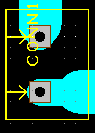
A fourth is the suggestion I made before, which is settle for the best compromise. I would accept that the relay contacts are as close together as they happen to be, so take the traces as wide as possible apart starting from the relay contacts. You can use a short track length of a narrow width (e.g. 1mm) and then immediately widen it out to a larger width. It'll look something like this:
The pin ends up at the edge of the track, so to speak. I this example, the minimal distance between the HV traces is 2.5mm, but this distance increases immediately as we move away from the closely-spaced contacts.
The rationale might be threefold:
1: The AC rated cap will be rated for the voltage it's actually used at; so it prevents the 2.8 multiplication factor issue ("It's 230V so let's use a 230V rated cap" - forgetting that 230VAC is a different animal than 230VDC)
2: The cap will be suited for AC use; i.e. it's non-polar.
3: The cap will be intended for HV-AC use from a safety point of view; i.e. it's made to fail open instead of fail short, and does not present a fire hazard upon failure.
Just guessing based on what you say you've read somewhere, of course; these are the things I can think of that people might have in mind when giving such advice.
According to the relay datasheet, the holes should be 1.5mm, 2.5mm is way to big. The pads for the relay should be at least 2.5mm in diameter.
I don't know the length of your traces so I don't know if 2.5mm is too small for your max current but I think you know how to figure that out.
The most important spacing constraint is between the low voltage stuff and the high voltage stuff. Use common sense, a few mm is probably not a good idea, make it as large as you can.
Don't run traces between the relay pins.
This is just a hobby project so following IEC and UL requirements isn't strictly necessary
There are two types of AC-rated capacitors: X and Y.
Basically - X fail short circuit and
Y fail open circuit.
The X and Y ratings have various agency (TUV, UL, CE mark) approvals.
"What is wrong is to say that you can only use AC rated capacitors for a snubber."
We'll have to agree to disagree.
No, that's not the type you would use in a switch box of a house. In fact, a switch box in a house generally doesn't involve any relays, and if they would, they would be some kind of rail-mounted relays.
See @jim-p's remark above; the holes should be around 1.6-1.8mm for 1.5mm diameter pins. They're also spaced >10mm apart, so you have plenty of space to work with. I think you can work this out.
"Mandatory"?
From my point of view - it's prudent.
A 'Y' type, because if it fails it will only stop snubbering (no sense taking out a fuse on that account).
Does this rig use a circuit breaker or have a fuse?
Never, ever, ever, EVER create a piece of equipment that connects to a wall socket without including a fuse. EVER. Unless you have a very solid reason for doing so (i.e. a fuse is technically not feasible). This is not such a case.
What would you suggest how I should implement that fuse?
I've never seen a relay module that has those glass fuses on the PCB itsself, so the fuse would be somewhere outside the PCB?
Yet I am thinking: even if there is a short between the relay's COM and NO pins, this would only power the devices regularly.
The danger would be mostly in the snubber circuit, and that would either cause the reistor or capacitor to burn out, or causing the apartments fuse to disconnect power?
You're making a PCB, so you're free to put fuses anywhere you want.
In your case, I'd put a fuse holder for a regular glass fuse on the HV-AC side of the PCB, and an SMT resettable 'polyfuse' on the low-voltage side of your project.
What you're forgetting is that the failure modes in the real world are exceedingly complex and numerous. If your line of thinking would hold true, there would never be any kind of industrial disaster. After all - if everything goes as planned, nothing goes wrong. It's the unanticipated things that bite you.
It's the water leak above your device that results in the PCB flooding, creating a short.
It's the inadvertent connection of the 2kW space heater due to mislabeling/lack of labeling of cables.
It's the screwdriver dropped while working on something else nearby and you forgot to pull the plug on this device first.
It's the Y-type capacitor failing short instead of open as it should have and the carbonized remains creating a micro-furnace setting fire to your PCB.
Etc. etc.
I can hear you say "but none of that applies, because there's no waterline/roof/etc over this module, I have no space heater, I don't use screwdrivers" and so on. The gist, however, is Murphy. Something will at some point go wrong, at that point you'll realize you could have known this all along but never imagined it, and at that point you'll (1) be happy that you put in that $0.50 fuse, replace it and have a beer or (2) be busy taking stock of damage and fixing stuff (best case scenario; might also involve calling the fire department and haggling with insurance).
This is really about risk management, and taking a cheap insurance against the small odds of a high-impact event. It's just sensible. That's why you include a fuse.
A short in the snubber won't cause a circuit breaker to trip, you juat won't be able to turn anything off.
If the capacitor or resistor fails how will that cause a fuse to blow?
I thought that if the membrane of the capactor fails, there would be a direct path between the brown and blue cable causing a lot of amps to flow
but yes, before I order the PCB, I will have to look into that topic and do some further reading of the things @rsmls says